element14 Community
element14 Community
    Register Log In
  • Site
  • Search
  • Log In Register
  • Community Hub
    Community Hub
    • What's New on element14
    • Feedback and Support
    • Benefits of Membership
    • Personal Blogs
    • Members Area
    • Achievement Levels
  • Learn
    Learn
    • Ask an Expert
    • eBooks
    • element14 presents
    • Learning Center
    • Tech Spotlight
    • STEM Academy
    • Webinars, Training and Events
    • Learning Groups
  • Technologies
    Technologies
    • 3D Printing
    • FPGA
    • Industrial Automation
    • Internet of Things
    • Power & Energy
    • Sensors
    • Technology Groups
  • Challenges & Projects
    Challenges & Projects
    • Design Challenges
    • element14 presents Projects
    • Project14
    • Arduino Projects
    • Raspberry Pi Projects
    • Project Groups
  • Products
    Products
    • Arduino
    • Avnet & Tria Boards Community
    • Dev Tools
    • Manufacturers
    • Multicomp Pro
    • Product Groups
    • Raspberry Pi
    • RoadTests & Reviews
  • About Us
    About the element14 Community
  • Store
    Store
    • Visit Your Store
    • Choose another store...
      • Europe
      •  Austria (German)
      •  Belgium (Dutch, French)
      •  Bulgaria (Bulgarian)
      •  Czech Republic (Czech)
      •  Denmark (Danish)
      •  Estonia (Estonian)
      •  Finland (Finnish)
      •  France (French)
      •  Germany (German)
      •  Hungary (Hungarian)
      •  Ireland
      •  Israel
      •  Italy (Italian)
      •  Latvia (Latvian)
      •  
      •  Lithuania (Lithuanian)
      •  Netherlands (Dutch)
      •  Norway (Norwegian)
      •  Poland (Polish)
      •  Portugal (Portuguese)
      •  Romania (Romanian)
      •  Russia (Russian)
      •  Slovakia (Slovak)
      •  Slovenia (Slovenian)
      •  Spain (Spanish)
      •  Sweden (Swedish)
      •  Switzerland(German, French)
      •  Turkey (Turkish)
      •  United Kingdom
      • Asia Pacific
      •  Australia
      •  China
      •  Hong Kong
      •  India
      •  Japan
      •  Korea (Korean)
      •  Malaysia
      •  New Zealand
      •  Philippines
      •  Singapore
      •  Taiwan
      •  Thailand (Thai)
      •  Vietnam
      • Americas
      •  Brazil (Portuguese)
      •  Canada
      •  Mexico (Spanish)
      •  United States
      Can't find the country/region you're looking for? Visit our export site or find a local distributor.
  • Translate
  • Profile
  • Settings
Community Hub
Community Hub
Member's Forum Using 12v at base of transistor
  • Blog
  • Forum
  • Documents
  • Quiz
  • Events
  • Leaderboard
  • Polls
  • Files
  • Members
  • Mentions
  • Sub-Groups
  • Tags
  • More
  • Cancel
  • New
Join Community Hub to participate - click to join for free!
Actions
  • Share
  • More
  • Cancel
Forum Thread Details
  • State Verified Answer
  • Replies 29 replies
  • Answers 10 answers
  • Subscribers 631 subscribers
  • Views 7913 views
  • Users 0 members are here
  • transistor
  • 12v
  • car
Related

Using 12v at base of transistor

ntewinkel
ntewinkel over 10 years ago

Hi all,


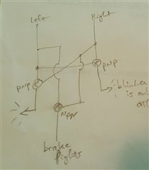
I'm thinking of using a transistor in a car circuit, to switch a light depending on the state of another light.


So it will be 12v as the signal at the base of the transistor.


I have a bunch of pn2222a transistors, and I can't figure out from the datasheet what the maximum means for that. It seems to be a reverse maximum (ie, don't let the output be more than 5v over the base voltage).


So the question is - is it possible to switch a transistor like that using 12v at the base?


Thanks!

-Nico


ps, I know I can easily do this using relays, but those take up more space, and I'd prefer to avoid the mechanical bits.

  • Sign in to reply
  • Cancel
Parents
  • ntewinkel
    0 ntewinkel over 10 years ago

    Dang, I just realized a logic error in my design!! Noooo!!


    Consider brakes are on at an intersection, and turning right.


    I just tested this on the 4-wire tailer harness in the car.


    In that case the left light stays on, and the right light flashes - and by that I mean there's steady 12v on the left wire, with 12v/0v on the right wire.


    Using my logic, when both lights are on, the red brake lights will be on (good),

    BUT when the flashing right light is off, the left light will be the only one on, which using my logic, will make it show the left orange arrow...


    so then the result looks like "red brake lights" intermittent with "left orange turn light"... giving the impression that we're turning in the opposite direction that we're actually going.


    Dang!

    This just got a whole lot more complicated!


    Anyone have any brilliant ideas?


    Maybe a large capacitor can keep the "signal" high for enough time to allow the other side to flash without switching to the orange arrow. But then the right turn would only flash the red light, not the arrow. Which is no different from how a regular trailer does it.


    I could also run an extra line from the car for the brake signal, but that would be non-standard and the trailer would still have to handle the case where some other vehicle is towing it.


    I'm wondering if I need to step this up to microcontroller control. The microcontroller can be kept powered on from the trailer battery. But then the failsafe (controller off or dead) needs to still give some sort of proper indications.


    For the time being I might just wire up the arrow and the red part together, with the side effect being that the brake signal will include both orange arrows on.


    Thanks,

    -Nico

    • Cancel
    • Vote Up 0 Vote Down
    • Sign in to reply
    • Verify Answer
    • Cancel
Reply
  • ntewinkel
    0 ntewinkel over 10 years ago

    Dang, I just realized a logic error in my design!! Noooo!!


    Consider brakes are on at an intersection, and turning right.


    I just tested this on the 4-wire tailer harness in the car.


    In that case the left light stays on, and the right light flashes - and by that I mean there's steady 12v on the left wire, with 12v/0v on the right wire.


    Using my logic, when both lights are on, the red brake lights will be on (good),

    BUT when the flashing right light is off, the left light will be the only one on, which using my logic, will make it show the left orange arrow...


    so then the result looks like "red brake lights" intermittent with "left orange turn light"... giving the impression that we're turning in the opposite direction that we're actually going.


    Dang!

    This just got a whole lot more complicated!


    Anyone have any brilliant ideas?


    Maybe a large capacitor can keep the "signal" high for enough time to allow the other side to flash without switching to the orange arrow. But then the right turn would only flash the red light, not the arrow. Which is no different from how a regular trailer does it.


    I could also run an extra line from the car for the brake signal, but that would be non-standard and the trailer would still have to handle the case where some other vehicle is towing it.


    I'm wondering if I need to step this up to microcontroller control. The microcontroller can be kept powered on from the trailer battery. But then the failsafe (controller off or dead) needs to still give some sort of proper indications.


    For the time being I might just wire up the arrow and the red part together, with the side effect being that the brake signal will include both orange arrows on.


    Thanks,

    -Nico

    • Cancel
    • Vote Up 0 Vote Down
    • Sign in to reply
    • Verify Answer
    • Cancel
Children
  • ntewinkel
    0 ntewinkel over 10 years ago in reply to ntewinkel

    ps, this is the circuit I had:

    image


    And a video showing how all works well until you press the brakes (both switches on) while blinking one side:

    You don't have permission to edit metadata of this video.
    Edit media
    x
    image
    Upload Preview
    image

    • Cancel
    • Vote Up 0 Vote Down
    • Sign in to reply
    • Verify Answer
    • Cancel
  • michaelkellett
    0 michaelkellett over 10 years ago in reply to ntewinkel

    Hello, I think I can do the right thing with one transistor and one relay but it needs to be double pole changeover.


    When both turn lines are high the relay will energize because its coil is connected between  LT and a transistor switched on by RT. When the relay is on it routes LT and RT to the brake lights, when it is off LT and RT go to the turn indicators.


    I'll scribble a circuit for you later today if I get a moment (or too bored with the real work !!).


    MK

    • Cancel
    • Vote Up +1 Vote Down
    • Sign in to reply
    • Verify Answer
    • Reject Answer
    • Cancel
element14 Community

element14 is the first online community specifically for engineers. Connect with your peers and get expert answers to your questions.

  • Members
  • Learn
  • Technologies
  • Challenges & Projects
  • Products
  • Store
  • About Us
  • Feedback & Support
  • FAQs
  • Terms of Use
  • Privacy Policy
  • Legal and Copyright Notices
  • Sitemap
  • Cookies

An Avnet Company © 2026 Premier Farnell Limited. All Rights Reserved.

Premier Farnell Ltd, registered in England and Wales (no 00876412), registered office: Farnell House, Forge Lane, Leeds LS12 2NE.

Follow element14

  • X
  • Facebook
  • linkedin
  • YouTube