


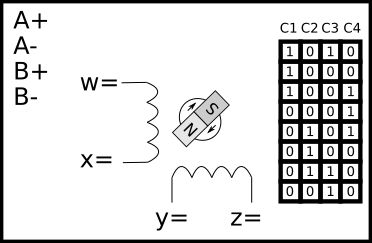
Assign the labels (A+, A-, B+, B- ) to the pins (w,x,y,z) on the motor windings and to the columns (C1, C2, C3, C4) of the table, that will enable the shaft to rotate in the clockwise direction. The sequence that the voltage is applied to the motor pins is shown in the table.
Your answer should be in the form w=A+...z=B- & C1=A+….C4=B-. No these examples are not the start of the answer.
I suspect I have incorrect manufacture documentation. The documentation indicates the step sequence for the stepper motor will rotate the shaft clockwise. The stepper motor does rotate in a clockwise direction with the sequence provided but stepper motor theory would suggest otherwise.
I have exhausted my stepper motor knowledge to make sense of the vendor drawings. If I use the motor pinout and winding diagram from the documentation with my understanding of motors the shaft should rotate anticlockwise with the sequence provided. I have used my theory knowledge to test against other vendors motors and it appears correct. When I make one pinout change on the vendors drawing the sequence and the rotation match motor theory.
I have a personally that can't ignore such a conflict. WHO CARES IT WORKS! I wish at times, I was one of those people. I have worked this problem off and on for a few days and can’t seem to resolve the conflict. My solution, create a discussion quiz and see what the E14 Community members can provide. I'm hoping your answers will match my understanding:)

