element14 Community
element14 Community
    Register Log In
  • Site
  • Search
  • Log In Register
  • Community Hub
    Community Hub
    • What's New on element14
    • Feedback and Support
    • Benefits of Membership
    • Personal Blogs
    • Members Area
    • Achievement Levels
  • Learn
    Learn
    • Ask an Expert
    • eBooks
    • element14 presents
    • Learning Center
    • Tech Spotlight
    • STEM Academy
    • Webinars, Training and Events
    • Learning Groups
  • Technologies
    Technologies
    • 3D Printing
    • FPGA
    • Industrial Automation
    • Internet of Things
    • Power & Energy
    • Sensors
    • Technology Groups
  • Challenges & Projects
    Challenges & Projects
    • Design Challenges
    • element14 presents Projects
    • Project14
    • Arduino Projects
    • Raspberry Pi Projects
    • Project Groups
  • Products
    Products
    • Arduino
    • Avnet Boards Community
    • Dev Tools
    • Manufacturers
    • Multicomp Pro
    • Product Groups
    • Raspberry Pi
    • RoadTests & Reviews
  • Store
    Store
    • Visit Your Store
    • Choose another store...
      • Europe
      •  Austria (German)
      •  Belgium (Dutch, French)
      •  Bulgaria (Bulgarian)
      •  Czech Republic (Czech)
      •  Denmark (Danish)
      •  Estonia (Estonian)
      •  Finland (Finnish)
      •  France (French)
      •  Germany (German)
      •  Hungary (Hungarian)
      •  Ireland
      •  Israel
      •  Italy (Italian)
      •  Latvia (Latvian)
      •  
      •  Lithuania (Lithuanian)
      •  Netherlands (Dutch)
      •  Norway (Norwegian)
      •  Poland (Polish)
      •  Portugal (Portuguese)
      •  Romania (Romanian)
      •  Russia (Russian)
      •  Slovakia (Slovak)
      •  Slovenia (Slovenian)
      •  Spain (Spanish)
      •  Sweden (Swedish)
      •  Switzerland(German, French)
      •  Turkey (Turkish)
      •  United Kingdom
      • Asia Pacific
      •  Australia
      •  China
      •  Hong Kong
      •  India
      •  Korea (Korean)
      •  Malaysia
      •  New Zealand
      •  Philippines
      •  Singapore
      •  Taiwan
      •  Thailand (Thai)
      • Americas
      •  Brazil (Portuguese)
      •  Canada
      •  Mexico (Spanish)
      •  United States
      Can't find the country/region you're looking for? Visit our export site or find a local distributor.
  • Translate
  • Profile
  • Settings
Community Hub
Community Hub
Member's Forum R&S FPC1500 - response below 2.5MHz?
  • Blog
  • Forum
  • Documents
  • Quiz
  • Events
  • Leaderboard
  • Polls
  • Files
  • Members
  • Mentions
  • Sub-Groups
  • Tags
  • More
  • Cancel
  • New
Join Community Hub to participate - click to join for free!
Actions
  • Share
  • More
  • Cancel
Forum Thread Details
  • State Suggested Answer
  • Replies 3 replies
  • Answers 2 answers
  • Subscribers 506 subscribers
  • Views 783 views
  • Users 0 members are here
Related

R&S FPC1500 - response below 2.5MHz?

dc2daylight
dc2daylight over 4 years ago

Hello,

I am new to this forum and my FPC1500 and have a technical question for someone who has some experience with this unit.  I learned so much from the fantastic review on the forum by shabaz.  It's a really nice piece of equipment and  have really been enjoying using it.

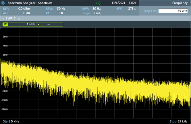
With no input signal I am seeing what I feel is an unexpected response below 2.5 MHz.   I will attach some pics to demonstrate.  I first noticed this on powering up or on a preset a yellow line spike can be seen on the far left of the screen going all the way to the top of the screen.  This is there but hard to see in the screen shot.   When the frequency span is adjusted it is clear that the noise floor rises rapidly below 2.5 MHz.  (see pic #2)   The data sheet indicates a 5 KHz - 3 GHz operating  bandwidth.    I have gone through some of the specs and it seems otherwise to be operating within them.  Am I seeing a normal and expected behavior or is there an incorrect setting or something misbehaving?   Lowering the BW limits do improve this but there is still a sharp rise approaching 5 KHz. rise .  Perhaps this is a just a firmware glitch?  (Firmware v1.60)

I appreciate any input.  Thanks in advance.


Mark

Attachments:
image
image
  • Sign in to reply
  • Cancel

Top Replies

  • shabaz
    shabaz over 4 years ago +6 suggested
    Hi Mark, If you want to get the lowest line visible on the SA, the resolution bandwidth needs to be reduced to as low as possible, otherwise it is showing the power across that value (generally, although…
  • dc2daylight
    dc2daylight over 4 years ago in reply to shabaz +2
    Thanks for taking the time with that explanation shabaz. I realize that this is not designed as audio spectrum analyser. Just wanted to make sure everything is operating appropriately. (except for this…
  • shabaz
    shabaz over 4 years ago in reply to dc2daylight +1 suggested
    Hi Mark, No problem, I'm a beginner at a lot of the features within the FPC1500 too... I feel at some point the features of test equipment advanced rapidly and especially spectrum analyzers (but also …
  • shabaz
    0 shabaz over 4 years ago

    Hi Mark,


    If you want to get the lowest line visible on the SA, the resolution bandwidth needs to be reduced to as low as possible, otherwise it is showing the power across that value (generally, although it depends on the shape of the internal filter). So in this case, the power in 1 MHz of spectrum is being displayed, but the FPC1500 can be set down to 1 Hz, although then that means the sweep rate becomes impractical, unless the span is greatly reduced, so it becomes a compromise.

    Also, the noise floor is only specified from 1 MHz in the datasheet. Generally most spectrum analyzers will not perform well at these very low frequencies, if the performance metric is the noise floor, however they are still usable at those frequency ranges.

    Here's my attempt for a 5kHz to 55kHz range (with 50 ohm terminator at the input), at 30 Hz resolution bandwidth, which took almost 6 minutes to complete a single sweep, so at 1 Hz it would have been much better, but would have taken too long.


    image


    At the 30 Hz resolution bandwidth, at 5 kHz the noise level is perhaps -55 dBm (will reduce with averaging), and it rapidly improves, so that at 55 kHz it is below -80 dBm (and again averaging, or a lower resolution bandwidth, or using the preamplifier, all will improve it).

    • Cancel
    • Vote Up +6 Vote Down
    • Sign in to reply
    • Verify Answer
    • Reject Answer
    • Cancel
  • dc2daylight
    0 dc2daylight over 4 years ago in reply to shabaz

    Thanks for taking the time with that explanation shabaz.  I realize that this is not designed as audio spectrum analyser. Just wanted to make sure everything is operating appropriately. (except for this inexperienced operator !  image ) Looks like everything is working as it should then.  I was able to reproduce the identical sweep as your screen shot above and confirmed all is working well.  I have been going through all the modes and features systematically.  Still using your review for a reference.  Having loads of fun with it.  Now fumbling around with the VNA capabilities with which I have really no experience.  For example, I noticed that the sweep bandwidth is more limited and some of the settings that are available in spectrum mode are not available in VNA mode.  I assume that is a technical reason for that. 

    • Cancel
    • Vote Up +2 Vote Down
    • Sign in to reply
    • Verify Answer
    • Cancel
  • shabaz
    0 shabaz over 4 years ago in reply to dc2daylight

    Hi Mark,


    No problem, I'm a beginner at a lot of the features within the FPC1500 too... I feel at some point the features of test equipment advanced rapidly and especially spectrum analyzers (but also 'scopes etc) started embedding programmed-in capabilities that might take years/decades for individuals to fully understand the underlying operations, so users end up having to rely a lot on the built-in features, but at least it provides productivity!

    For the VNA feature, the lower limit is 2 MHz, and the reason will be because internally it needs to have a bridge or coupler type of component to see the reflected signal, and they are hard to implement to operate well over the huge frequency range (and it would get pricey to switch in a different component for that for different ranges). There could be other differences too, due to the fact that the measurement occurs from the other port on the spectrum analyser, so there will be feature or performance differences.

    • Cancel
    • Vote Up +1 Vote Down
    • Sign in to reply
    • Verify Answer
    • Reject Answer
    • Cancel
element14 Community

element14 is the first online community specifically for engineers. Connect with your peers and get expert answers to your questions.

  • Members
  • Learn
  • Technologies
  • Challenges & Projects
  • Products
  • Store
  • About Us
  • Feedback & Support
  • FAQs
  • Terms of Use
  • Privacy Policy
  • Legal and Copyright Notices
  • Sitemap
  • Cookies

An Avnet Company © 2025 Premier Farnell Limited. All Rights Reserved.

Premier Farnell Ltd, registered in England and Wales (no 00876412), registered office: Farnell House, Forge Lane, Leeds LS12 2NE.

ICP 备案号 10220084.

Follow element14

  • X
  • Facebook
  • linkedin
  • YouTube