element14 Community
element14 Community
    Register Log In
  • Site
  • Search
  • Log In Register
  • Community Hub
    Community Hub
    • What's New on element14
    • Feedback and Support
    • Benefits of Membership
    • Personal Blogs
    • Members Area
    • Achievement Levels
  • Learn
    Learn
    • Ask an Expert
    • eBooks
    • element14 presents
    • Learning Center
    • Tech Spotlight
    • STEM Academy
    • Webinars, Training and Events
    • Learning Groups
  • Technologies
    Technologies
    • 3D Printing
    • FPGA
    • Industrial Automation
    • Internet of Things
    • Power & Energy
    • Sensors
    • Technology Groups
  • Challenges & Projects
    Challenges & Projects
    • Design Challenges
    • element14 presents Projects
    • Project14
    • Arduino Projects
    • Raspberry Pi Projects
    • Project Groups
  • Products
    Products
    • Arduino
    • Avnet Boards Community
    • Dev Tools
    • Manufacturers
    • Multicomp Pro
    • Product Groups
    • Raspberry Pi
    • RoadTests & Reviews
  • About Us
  • Store
    Store
    • Visit Your Store
    • Choose another store...
      • Europe
      •  Austria (German)
      •  Belgium (Dutch, French)
      •  Bulgaria (Bulgarian)
      •  Czech Republic (Czech)
      •  Denmark (Danish)
      •  Estonia (Estonian)
      •  Finland (Finnish)
      •  France (French)
      •  Germany (German)
      •  Hungary (Hungarian)
      •  Ireland
      •  Israel
      •  Italy (Italian)
      •  Latvia (Latvian)
      •  
      •  Lithuania (Lithuanian)
      •  Netherlands (Dutch)
      •  Norway (Norwegian)
      •  Poland (Polish)
      •  Portugal (Portuguese)
      •  Romania (Romanian)
      •  Russia (Russian)
      •  Slovakia (Slovak)
      •  Slovenia (Slovenian)
      •  Spain (Spanish)
      •  Sweden (Swedish)
      •  Switzerland(German, French)
      •  Turkey (Turkish)
      •  United Kingdom
      • Asia Pacific
      •  Australia
      •  China
      •  Hong Kong
      •  India
      •  Korea (Korean)
      •  Malaysia
      •  New Zealand
      •  Philippines
      •  Singapore
      •  Taiwan
      •  Thailand (Thai)
      • Americas
      •  Brazil (Portuguese)
      •  Canada
      •  Mexico (Spanish)
      •  United States
      Can't find the country/region you're looking for? Visit our export site or find a local distributor.
  • Translate
  • Profile
  • Settings
Community Hub
Community Hub
Member's Forum Hello, new here with a question regarding Lpad resistors.
  • Blog
  • Forum
  • Documents
  • Quiz
  • Events
  • Leaderboard
  • Polls
  • Files
  • Members
  • Mentions
  • Sub-Groups
  • Tags
  • More
  • Cancel
  • New
Join Community Hub to participate - click to join for free!
Actions
  • Share
  • More
  • Cancel
Forum Thread Details
  • State Suggested Answer
  • Replies 17 replies
  • Answers 7 answers
  • Subscribers 548 subscribers
  • Views 3690 views
  • Users 0 members are here
  • lpad
  • Speakers
Related

Hello, new here with a question regarding Lpad resistors.

mrsouth
mrsouth over 4 years ago

First of I'm new so Hi, 

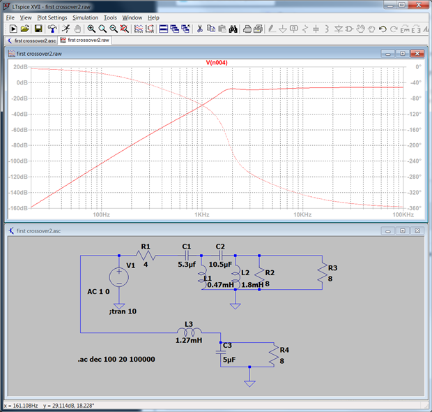
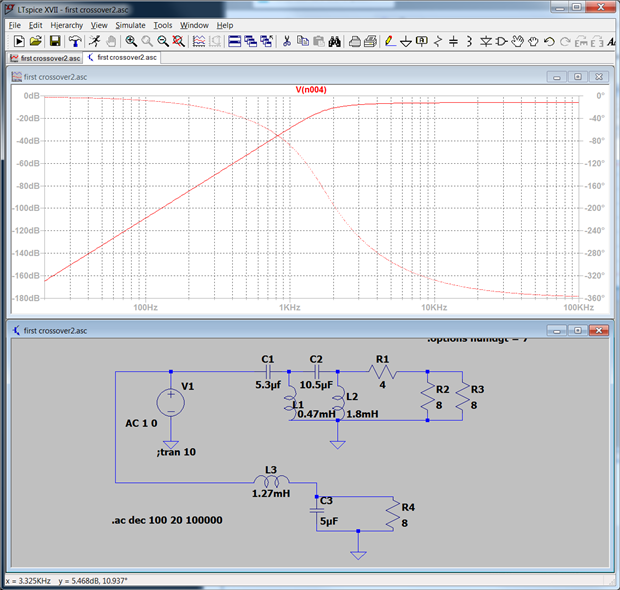
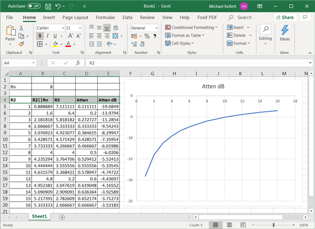
     I have been messing about with Lpads (I have a few horns I need to tame in P.A enclosures).  I have created a crossover in LTspice, added the appropriate Lpad resistor values then I ran a simulation to check everything over.  First the voltage supply was set to 56V (level required to drive 8 ohm speakers to their rated 400Watts) and set it as a sine wave at 8Khz.  The crossover and Lpad are definitely working as designed (tested with pink noise source and checked fourier as well), however the the first Resistor in the Lpad (R1) is dissipating 120Watts.    Which seems at odds with the 30Watt resistors I've seen in similar rated speaker cabs.  Our overlord google.com has told me they don't need to be high wattage resistors,  but the circuit and simulation here (designed using commonly available calculators) tells me otherwise.


image

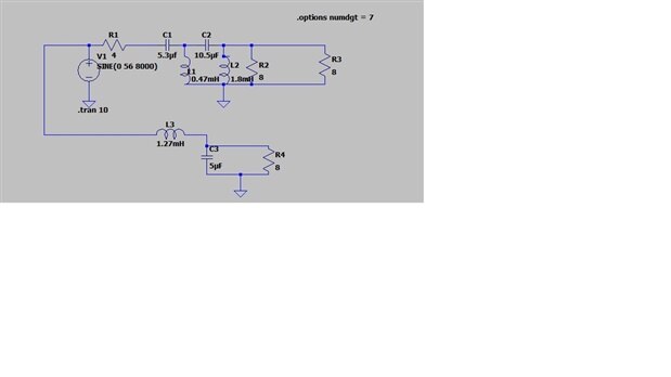
R1 and R2 are the Lpad, R3 is the horn.

The rest being a 4th order for the horn and 2nd order for the woofer.


Any Ideas what I am doing wrong?


Many thanks.


P.S still trying to work out how this site all works, forgive me if I've posted in the wrong group or something.

  • Sign in to reply
  • Cancel

Top Replies

  • shabaz
    shabaz over 4 years ago +6 suggested
    Hi Matthew, I didn't have a chance to read/examine this in detail, but what stuck out was that you simulated with a sine wave. That may explain why the real-life resistors are of a lower power rating,…
  • michaelkellett
    michaelkellett over 4 years ago in reply to shabaz +6 suggested
    Good point Shabaz - in real full range prgramme material the amount of energy at high frequencies will only be a small proprtion of the total. @ mrsouth Looking at the circuit, at high frequencies we can…
  • jc2048
    jc2048 over 4 years ago +5 suggested
    I don't understand anything about crossover design. What was the rationale for adding R2 to the circuit and lowering R1 to 4 Ohms to match? Is it because the horn is starting to look somewhat inductive…
  • mrsouth
    0 mrsouth over 4 years ago in reply to jc2048

    Thanks, again, you are right (although I think companies like LA acoustics and QSC might argue with you about the "fiddling around" image.    I don't mind fiddling as it is a hobby as much as a weekend earner (although not during covid times image).


    I will give that program a go,  from your screen shots it look similar to EWB (the program I learnt back in the 90's) Just missing the live readouts on the meters.


    It looks like you got the same outcome as I did,  I think I measured 122W across R1 (if I'm being accurate),  which if we account for average power and the fact that a music signal will likely be even less,  then it seems everyone has come to basically the same conclusion.  My mistake was not accounting for that.    I will find an actual music source and run the simulation again.


    Thank you to everyone who posted, you have all been very helpful.


    MS

    • Cancel
    • Vote Up +1 Vote Down
    • Sign in to reply
    • Verify Answer
    • Cancel
  • michaelkellett
    0 michaelkellett over 4 years ago in reply to mrsouth

    I think you have R1 in the wrong place - the idea of the Lpad is to make two resistors look like the same impedance to the drive source.


    R1 in orignal position, filter sees 4R load and 4R source

    image


    R2 in correct position, filter sees 8R load and 0R source


    image


    I expect that you know that you will get much better results with an active crossover and two power amps.


    What drivers are you using ?


    You can buy a 100 W Lpad at a very reasonable price:

    https://cpc.farnell.com/monacor/at-62h/high-power-l-pad-mono/dp/LS00547


    I'm not that confident about the power rating but I think it would be OK for the HF driver.


    might be worth just tuning it by ear.


    MK

    • Cancel
    • Vote Up +1 Vote Down
    • Sign in to reply
    • Verify Answer
    • Reject Answer
    • Cancel
  • mrsouth
    0 mrsouth over 4 years ago in reply to michaelkellett

    Thanks Michael,  yes active and more amps is an ideal long term goal.  At the moment though I need to keep the system simple.     If you look at your graphs you will see that with R1 before the filter the horn is several dB lower, but when it is after the filter the reduction is not there (or at least not as predicted by the calculator).      I think this is one of those trade off things where you have a triangle and you can only have two of the three.


    EDIT: I made a mistake reading your graphs, the upper range of one is 20db higher.  So while it looks like there is more attenuation on the second circuit, it might not be.    Something I need to look into before I make the final.

    MS

    • Cancel
    • Vote Up +1 Vote Down
    • Sign in to reply
    • Verify Answer
    • Cancel
  • michaelkellett
    0 michaelkellett over 4 years ago in reply to mrsouth

    If you need more attenuation then just alter the LPAD resistors.

    The rules are:

    Rn = R3 = 8 (impedance of horn driver), Rn||R2 is the impedance of the horn in parallel with R2

    Rn||R2 = 1/(1/R2 + 0.125)

    R1 = 8 - Rn||R2

    Attenuation = Rn||R2 / 8


    You can solve the equations (not before breakfast) so I did a little Excel spreadsheet:

    (all these tools make us lazy !)


    image


    MK

    • Cancel
    • Vote Up +1 Vote Down
    • Sign in to reply
    • Verify Answer
    • Reject Answer
    • Cancel
  • mrsouth
    0 mrsouth over 4 years ago in reply to michaelkellett

    If you're not careful you will make it too easy for me and I won't learn anything. image.


    Cheers for that,  Now I just need to get my act together and work out the power rating required for the resistors and build it.


    MS

    • Cancel
    • Vote Up +1 Vote Down
    • Sign in to reply
    • Verify Answer
    • Cancel
  • kkazem
    0 kkazem over 3 years ago in reply to michaelkellett

    With a 4 ohm series resistor and the 8 || 8-ohm = 4 ohm load, they form a voltage divider of 4/8 = 0.50 or 50% of the input maximum gets to the output. This means you lose half of your amplifier's output in R1. That's not a great design. There are better ways of designing low pass and high pass, passive filters that avoid high losses like this. A better way is to Bi-amp your amplifier by using two smaller amps that each have an active filter between the pre-amp and the power amp so that you avoid high losses in the filtering and virtually 100% of your amp's power goes to the load.

    • Cancel
    • Vote Up +2 Vote Down
    • Sign in to reply
    • Verify Answer
    • Cancel
  • mrsouth
    0 mrsouth over 3 years ago in reply to kkazem

    Cheers for chiming in kkazem.  I have taken the advice of active crossovers for my other speakers, however this one is powered by a single mixer/amp and needs to be a super simple/portable unit so bi amping is not an option.  Since starting this thread I have pulled apart a set of wharfedale PA drivers of similar size and found the crossover they designed to be even more perplexing than mine.   Although I haven't started yet (project had to go on the back burner) I am going to build the circuit below as altered by Michael Kellett, and give it thorough testing before making the second one.   If it turns out to be too problematic then I will likely replace the compression drivers with something less aggressive wh9ich should mean less issues with Lpad design.  

    • Cancel
    • Vote Up +2 Vote Down
    • Sign in to reply
    • Verify Answer
    • Cancel
<
element14 Community

element14 is the first online community specifically for engineers. Connect with your peers and get expert answers to your questions.

  • Members
  • Learn
  • Technologies
  • Challenges & Projects
  • Products
  • Store
  • About Us
  • Feedback & Support
  • FAQs
  • Terms of Use
  • Privacy Policy
  • Legal and Copyright Notices
  • Sitemap
  • Cookies

An Avnet Company © 2025 Premier Farnell Limited. All Rights Reserved.

Premier Farnell Ltd, registered in England and Wales (no 00876412), registered office: Farnell House, Forge Lane, Leeds LS12 2NE.

ICP 备案号 10220084.

Follow element14

  • X
  • Facebook
  • linkedin
  • YouTube