I'm mostly an embedded software person (lately more pure software). I'm getting the details of the requirements from a person that works as a protection engineer. After getting some feedback I'm going to try to provide some more information and re-phrase the question.
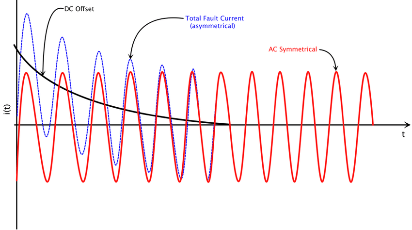
The ultimate goal is to convert a signal from a signal generator so that the voltage levels are high enough to work with the SEL 351S relay (without having to remove parts and wire things directly to the low voltage side internally). As some people suspected its intended to be part of a test bench for simulating fault conditions. The signal generator will be outputting something like the image below, with a maximum output range of +/-12V. As you can see the signal contains a DC offset during the fault condition.

Being a utility application the base frequency is 60Hz, but harmonics up to 1200Hz have to be considered. The goal is to scale the signal from +/- 12V to +/- 424V (I realize before I said 300V, but am now told its 300 * sqrt(2)). The scaled signal will be connected to an input impedance of 1 Mega Ohm on an SEL 351S relay. Someone pointed out the large disparity in input and output power (I was just being thrown numbers when I made the post). After examining things it shouldn't need anywhere near a quarter amp - it should be at most about .5ma max. Its not really driving a load; this is an input to a voltage sensor on the relay.
I hope this clarifies things.
I'm updating this to include that 10 channels are also required.
