Interesting point, misaz . As I’m relatively new here, an update on this thread made me revisit the whole discussion.
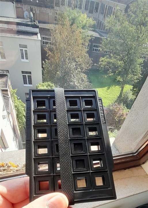
In a previous PCB design/manufacturing role (about 5 years ago) we still received some MCUs in trays, mainly for lower volumes. They were quite convenient for prototyping.
Maybe it’s more common now to default to reels depending on order size.
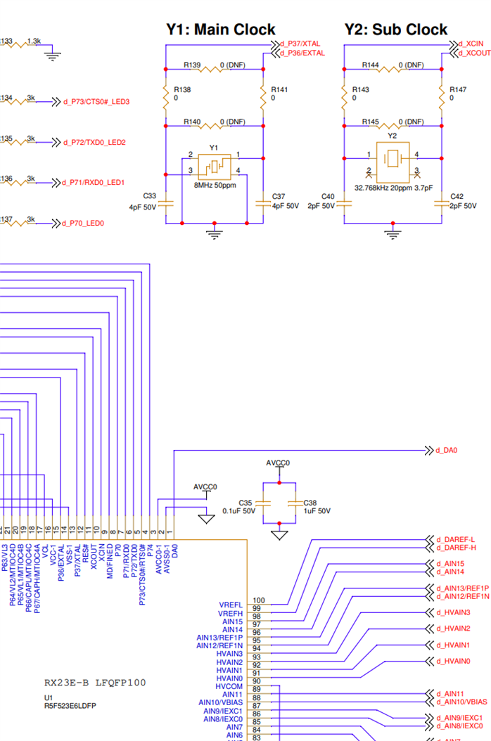
I'm making progress. The schematic is ready for anything that is not related to the analogue front end. I had to get that out of the way, before focusing on that part;
You don't have permission to edit metadata of this video.
If I manage to get the board designed (daytime job creeps into the nighttime at the moment), I can learn some more about properly designing the clock circuit ...
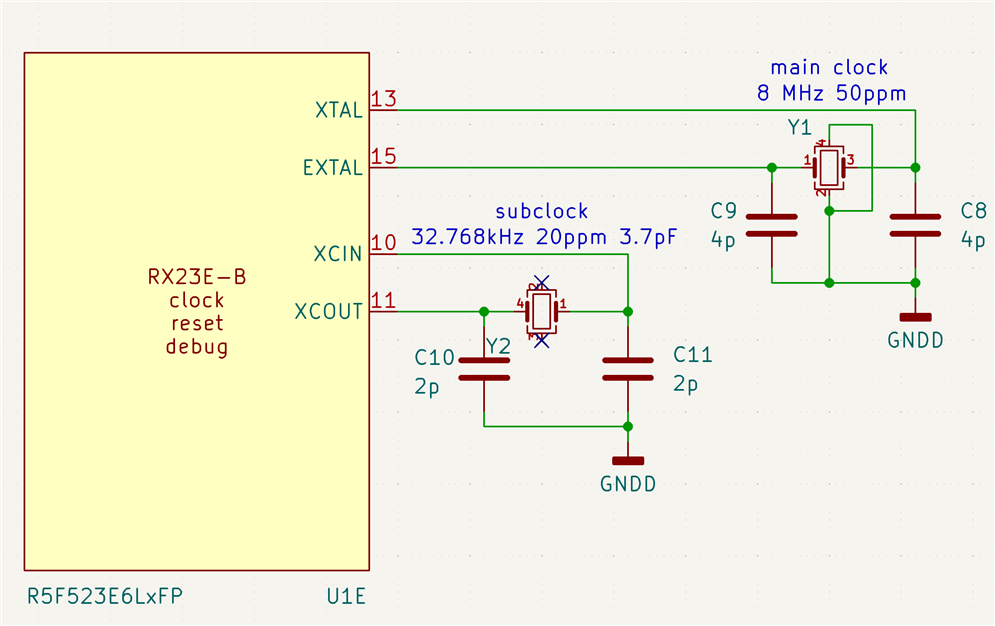
How curious. It would still work (it would probably work without any load caps and just the pin capacitance), but it would be a bit skittish and the RTC isn't going to keep very good time.
Where did the load caps come from? They look low in value to me.
If the 32.768kHz xtal is cut for 3.7pF, then assuming a pin/track value of something like 1.5pF (if you keep it compact and close to the pins), 5.6pF might work better. (5.6pF+1.5pF)/2 = 3.55pF