So I have been tasked to discover how a 'roller' garage door knows when it is fully UP or Down and it is mystifying me
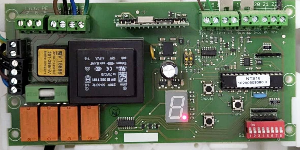
So here's all the information I have on the roller door controller. (pictured)
We took off the roller shutter cover inside the garage and all there is, is the skeleton roller mechanism with a square diecast looking housing that may be the motor connected to the roller at one end.
The 4 core power cable goes into the diecast housing/body and after some searching the web I discovered that this is a 'tube motor' whose body is hidden inside the roller centre tube.
The diecast housing has a 'manual' winder loop sticking out of it with which one can manually wind the door up and down with a hooked handle, so the housing may just be gearbox and/or clutch?
So there are 4 wires going to the motor. (entering the diecast housing)
Earth, Neutral and two switched lives (UP and DOWN)
My internet trawl seems to show that the motor has two sets of 240V windings in opposite arrangement to allow it to reverse.
As far as I can tell only one live wire is energised at a time. (one going up and the other for coming down).

The up and down are controlled by two of those four orange relays bottom left on the controller pcb.
A third relay seems to disable all motor power, (or to make sure both up and down can't be on together?)
The fourth operates the lightbulb on top of the controller box!
All the relays seem to be driven via relay drivers directly from the microcontroller.
There are NO other wires coming from outside the controller other than the rubber pressure sensor at the bottom of the door.
Which does work!
So NO visible limit switches
No shaft encoders or extra wires from the motor housing etc.
So how does it know to stop at the top and bottom?
Could it be simply 'timing' based?
Well I don't think so as clearly IF the door ONLY went fully up and then fully down then this may be feasible.
However one can stop the door anywhere and reverse it several times and it still doesn't lose its sense of fully up or down or where it is!
Also It can't use the pressure sensor as yes this would work for fully down, but what about fully at the top?
Current sensing?
Well we tried monitoring the running current and it was 1.4A a.c. and this didn't seem to increase when the door hit the floor. However this was with a DVM which may not have been quick enough)
Will take my AVOmeter next time.
A (I don't know which) relay clicks OFF just after the door is fully closed, but the sequence is - it closes, all the slats squeeze up and then a relay can be heard to click and stops the motor.
There doesn't seem to be any evidence of current sensing wire shunts (at least on the face of the pcb) which detracts from the current sensing theory. But there could be something on the back of the board.
I may have to strip it out to investigate further but before I dismantle the whole thing someone just may save me a whole lot of investigation by knowing the secret and would kindly share the 'spell'?
Thanks in anticipation
Dave
