So I have been tasked to discover how a 'roller' garage door knows when it is fully UP or Down and it is mystifying me
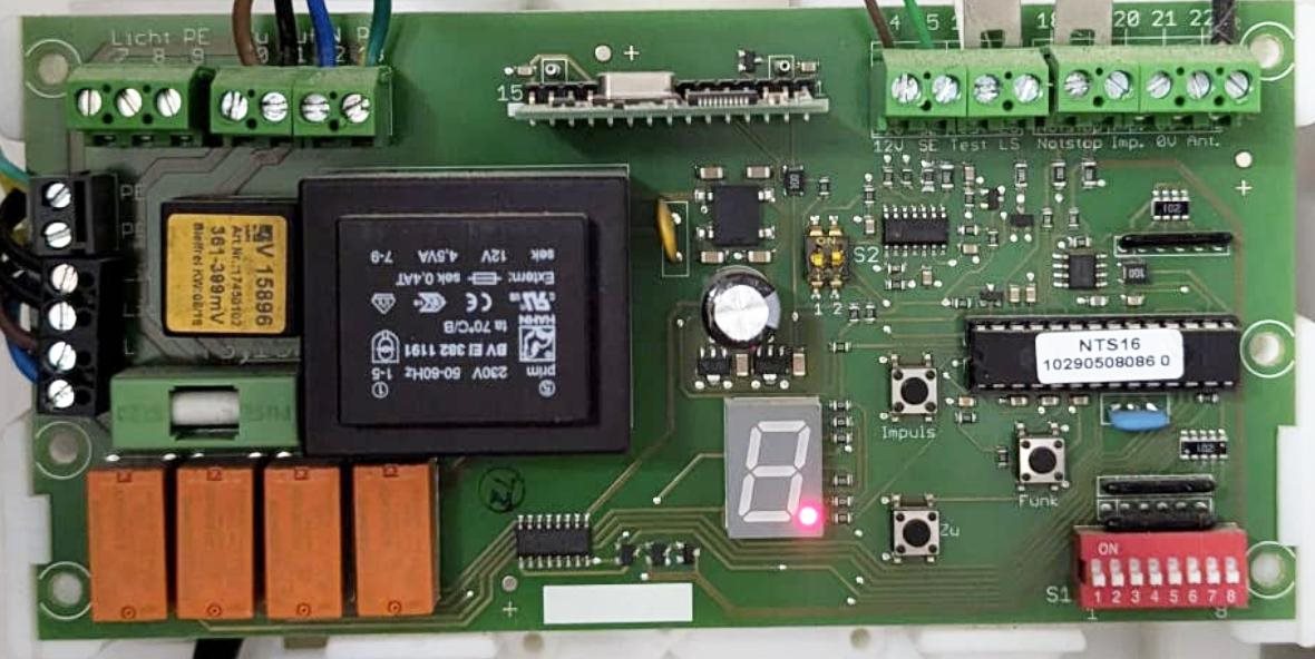
So here's all the information I have on the roller door controller. (pictured)

So I have been tasked to discover how a 'roller' garage door knows when it is fully UP or Down and it is mystifying me
So here's all the information I have on the roller door controller. (pictured)

davebullockmbe This video will probably help. https://www.youtube.com/watch?v=Oii3L1Uw_XU Looks like he could use a few likes. 2:10 to 2:50
Not a bad teardown video.
Hello Dave, I don't know why I am replying to dougw but there you go...
I once had a 12v 4A DC PSU with a very crude overcurrent protection system built in. This consisted of a DPDT relay that was connected in such a way that when the power came on nothing happened. A small normally-open push-button was then pressed to make the relay switch and one of the contact pairs made contact, thus latching the relay into the energised state. The other pair of contacts was connected in series with the 12v DC and the back of the red output terminal, so that (at last!) 12v DC appeared on the output terminals.
Here's the tricky bit. The latch part of all this had a carefully-selected resistor connected such that the current through the coil was only just enough to hold the relay in the energised state. The power supply output volyage was not particularly well regulated, so if the load on the output became too much the voltage would drop. This reduced voltage caused the coil to allow the latch to drop out and the whole thing would cease to function. Until the overload was sorted and the push-button pressed again.
Looking at the photo of your board it is obvious that the big black square thing is a transformer. The little square thing mounted close to it's left side and with a yellow label on it is intriguing. It has a rating on it measured in millivolts. This could mean all sorts of things, but it could be a far more sophisticated version of my overcurrent protection system whereby the quoted millivolts is the operating range? I can't read much of the printing on the label, but it might be worth typing some of it into a search engine and see what you get. Be very careful poking around with meter probes in that area, some of that wiring looks mighty powerful to me...
Because the smaller square thing with the yellow label is mounted so close to the transformer it could be some sort of heat sensor or maybe an inductive device that could measure the transformer current without any electrical connection. The green thing below it with the white bar across looks like a fuse in a green holder.
Where did you measure the running current? I would have expected the motor current to drop to zero when the door hit the floor - and what is the control system? Pushing a button might be engaging a latch at the same time as powering the motor, presumably one for each direction. As there are no semiconductors involved the latch and the relays would operate no matter which direction the current was flowing.
Good luck, and pleeeease don't electrify yourself.
That thing with the yellow label on it is probably a current transformer, since as you suggest, overcurent protection would be needed anyway. It also looks like the fat traces pass through there, adding more weight to that idea.
I've never looked at a garage door opener so I don't know if they would do anything additional, but definitely seems plausible that current sensing could play a role in detecting when to stop the motor as it approaches the limit (e.g. more friction). Or (apparently) you can detect how close to stalled you are, by monitoring the phase difference between the two windings (since a voltage appears across the unpowered winding). I don't know if it is that sophisticated though.
HI thanks for your thoughts so far.
Yes I have thought of 'carefully' trying to stall the roller half way down to see if it stops proving that there is some sort of current sensing.
I too spotted the mystery yellow labelled block with its mV range and wondered if this was a current transformer.
I also wondered about putting a diode in series with the motor supply to slow it down to disprove any 'timing' method of knowing where it is. But I think I have disproved this theory anyway.
The front cover is missing so there is no manufacturers information as to make or model ,although the roller itself has the name Novoferm emblazoned upon it.
I will continue to investigate.
Thanks
Dave
I think Novoferm is a Spanish company. You can look for Novoport or Novomatic here: Documentación técnica | Novoferm (novofermalsal.com)
Several Novoport versions share that layout

Hi and a BIG thank-you to all respondents the mystery is solved.
Whilst I was fully expecting any 'end of travel' limits to be relayed back to the controller, and the total lack of any evidence of limit switches on the roller mechanism I was baffled.
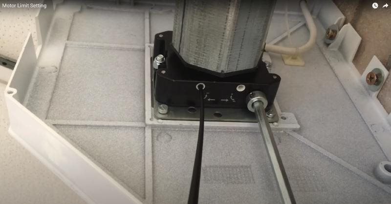
However the diecast box at one end of the roller was the magical answer.
The black box shown in the attached picture on the roller I have been musing over, was a silver (unpainted) box and the two white adjusters are black. Consequently they just looked like blank holes in the darkness of the garage roof. There are no printed arrows like in the pictured item.
The limit switches are concealed within the box and simply break the mains feed when the limit is reached.
I had no access to paperwork or any instructions until aided by your kind comments whereby I was able to search and actually find a YouTube video explaining how to adjust the 'said' limits.
So simple once you know the secret.
I am still wondering why the relay on the controller pcb clicks off after the door stops (rather than instantly) but this may still involve what looks like the yellow labelled (current?) transformer which would kind of make sense?
Whatever, maybe a case of 'not seeing the wood for the trees' the mystery is solved as far as my involvement is concerned.
Thank you all for your support and encouragement, "True community spirit"
Dave

Hi Just a note to say I work with a lot of these motors in electric blinds.
Normally the control box is dumb. It just activates the relay for a timed period. As you corrently found out the limits are within the motor. This is normally done for safty.
Quite often there is a current sensor in the control box so that if the motor is jamed it will kill the power. I expect in your case the limit switch kills the motor and then the controller then becomes open circit lead to its protection system releasing the relay.
We we install these motors we just have a toggle switch to send them up and down. No controll needed if this helps.
JT