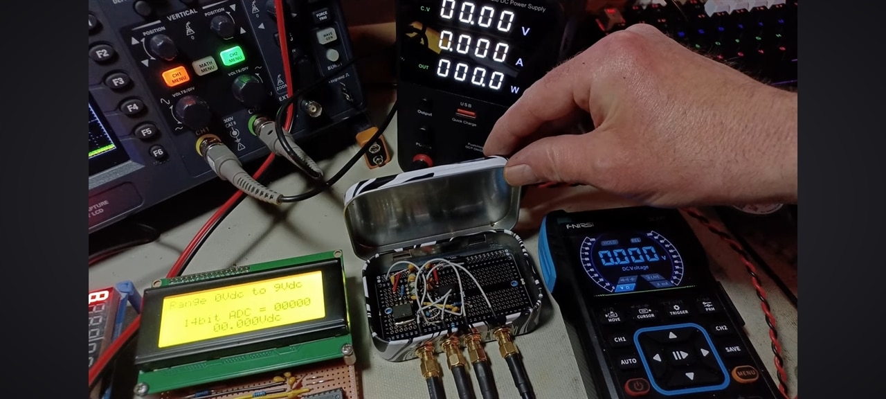
I have a video up on youtube of this working, it is based on a ramp counter, constant current linear ramp with comparator. I used an STC89C52 running at 20Mhz in 6T mode, this is based on the old 8051 microcontroller. With 20x4 LCD
A long time ago when an 8 bit monolithic ADC was expensive and the best you could buy was 12 bit, I had to design an auto ranging audio frequency level meter for BT. We wanted to be able to cover 14dB in each range with a worst case accuracy of 0.1dB which needs at least 10 bit resolution if you use a linear ADC. But if you use a logarithmic ADC you only need 140 divisions rather than 1024. A single slope log converter can be made by replacing the current source with a resistor. Two comparators rather than 1 enables you to auto-cal it on every conversion. But you needed a decent capacitor - think we used a 10nF polystyrene one.
But now you can buy an I2C interfaced 16 bit converter with two differential input ports, one with very low offset for under £1 (an INA230) so the art of single, dual and even multi-slope converters has had its day
Nice, mine is a linear dc voltage display with raw A to D count of 19716 counts at 9V input to give me mV resolution, gives me just over 14bit resolution, no software filtering and no software linearity correction, pure raw Analogue linearity.
Is it just for fun or do you need it for something ?
I've seen people do similar things when they need an unexpected ADC and only have IO pins available. But they don't get very good results with standard pins and the processor supply for reference.
but it is awesome to make and understand how these work, hp/agilent/keysight etc started out with dual slope adc and now have things like multislope or way more complex algorithms to significantly improve accuracy, how repeatable is your design both in accuracy and stability?
you should be able to find old schematics and descriptions of the older HP bench meters if you want to understand more about auto cal etc.
Thanks for sharing the schematic. I am assuming that while Ramp control is 0V the capacitor charges and when the comparator trips it is detected in software... so my question is... is the ADC value obtained by a counter that runs during the capacitor charge cycle? Or am I completely misunderstanding your design?
Thanks for sharing the schematic. I am assuming that while Ramp control is 0V the capacitor charges and when the comparator trips it is detected in software... so my question is... is the ADC value obtained by a counter that runs during the capacitor charge cycle? Or am I completely misunderstanding your design?
thanks, this is loosely based on a 1954 ramp counter principle.
begin, relese clamp start linear ramp charge, start For loop count, in the loop poll to detect comparator if not detected count increments, when comparator change detected stop count, display count value - reset counter and clamp ramp. repeat process.
the more linear the ramp is, the more accurate the ADC becomes.
Thanks. I guess I was on the right track then. I think commercial ADCs generally have an error that exceeds 1mV... so there is no shame in chasing 3mV or 4mV dragon.
And I guess you are in good company. Your Ramp Generator circuit resembles this one:
Think of it like a CR timer, C x R = T (time to charge) but instaid of a curved ramp you get a Linear ramp because I = is a constant current.
where R = V/I
then you have C x R = Time.
Sorry i can't give values but thats my secret sauce, being one of the very few to pull off a home built 14bit adc.
if you have a signal generator, then use that to enable / disable the ramp at the input to R2 in my sketch. or just pull low to start ramp and pull high 5V to stop ramp.
Sorry i can't give values but thats my secret sauce, being one of the very few to pull off a home built 14bit adc.
That's the part I don't get. Why post an experiment on a public forum, and then not share part of it "because secret". it's an ADC. What's the value of keeping this secret?
This was just a diy build in my flat at weekends and evenings, I don't have an environmental chamber in my front room, i was seeing if it was possible to get a 14bit adc stable and fairly linear. If you analyse my video below you will see what I have achieved