element14 Community
element14 Community
    Register Log In
  • Site
  • Search
  • Log In Register
  • Community Hub
    Community Hub
    • What's New on element14
    • Feedback and Support
    • Benefits of Membership
    • Personal Blogs
    • Members Area
    • Achievement Levels
  • Learn
    Learn
    • Ask an Expert
    • eBooks
    • element14 presents
    • Learning Center
    • Tech Spotlight
    • STEM Academy
    • Webinars, Training and Events
    • Learning Groups
  • Technologies
    Technologies
    • 3D Printing
    • FPGA
    • Industrial Automation
    • Internet of Things
    • Power & Energy
    • Sensors
    • Technology Groups
  • Challenges & Projects
    Challenges & Projects
    • Design Challenges
    • element14 presents Projects
    • Project14
    • Arduino Projects
    • Raspberry Pi Projects
    • Project Groups
  • Products
    Products
    • Arduino
    • Avnet & Tria Boards Community
    • Dev Tools
    • Manufacturers
    • Multicomp Pro
    • Product Groups
    • Raspberry Pi
    • RoadTests & Reviews
  • About Us
    About the element14 Community
  • Store
    Store
    • Visit Your Store
    • Choose another store...
      • Europe
      •  Austria (German)
      •  Belgium (Dutch, French)
      •  Bulgaria (Bulgarian)
      •  Czech Republic (Czech)
      •  Denmark (Danish)
      •  Estonia (Estonian)
      •  Finland (Finnish)
      •  France (French)
      •  Germany (German)
      •  Hungary (Hungarian)
      •  Ireland
      •  Israel
      •  Italy (Italian)
      •  Latvia (Latvian)
      •  
      •  Lithuania (Lithuanian)
      •  Netherlands (Dutch)
      •  Norway (Norwegian)
      •  Poland (Polish)
      •  Portugal (Portuguese)
      •  Romania (Romanian)
      •  Russia (Russian)
      •  Slovakia (Slovak)
      •  Slovenia (Slovenian)
      •  Spain (Spanish)
      •  Sweden (Swedish)
      •  Switzerland(German, French)
      •  Turkey (Turkish)
      •  United Kingdom
      • Asia Pacific
      •  Australia
      •  China
      •  Hong Kong
      •  India
      •  Japan
      •  Korea (Korean)
      •  Malaysia
      •  New Zealand
      •  Philippines
      •  Singapore
      •  Taiwan
      •  Thailand (Thai)
      •  Vietnam
      • Americas
      •  Brazil (Portuguese)
      •  Canada
      •  Mexico (Spanish)
      •  United States
      Can't find the country/region you're looking for? Visit our export site or find a local distributor.
  • Translate
  • Profile
  • Settings
Community Hub
Community Hub
Member's Forum Programable Gain Amplifier
  • Blog
  • Forum
  • Documents
  • Quiz
  • Events
  • Leaderboard
  • Polls
  • Files
  • Members
  • Mentions
  • Sub-Groups
  • Tags
  • More
  • Cancel
  • New
Join Community Hub to participate - click to join for free!
Actions
  • Share
  • More
  • Cancel
Forum Thread Details
  • Replies 11 replies
  • Subscribers 595 subscribers
  • Views 240 views
  • Users 0 members are here
Related

Programable Gain Amplifier

scottiebabe
scottiebabe 3 days ago

I have a project where I am in need of a amplifier with digitally adjustable gain.

There are many ways to construct a variable gain amplifier, one solution involves using a digital potentiometer in the negative feedback path around an op-amp.

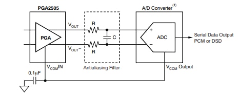
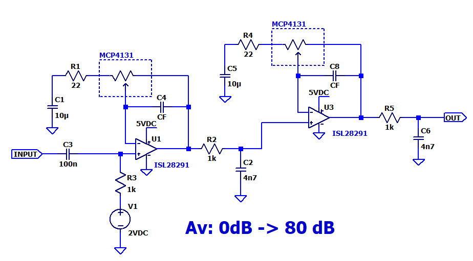
A simplified schematic is shown below

image

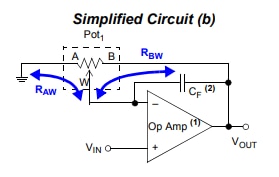
Image sourced from Application note: ww1.microchip.com/.../01316A.pdf

The closed loop gain of the amplifier is now a function of the digiPOT’s wiper position:

image
Table for an 8-bit digiPOT, table 12 for a 7-bit device is full of mistakes

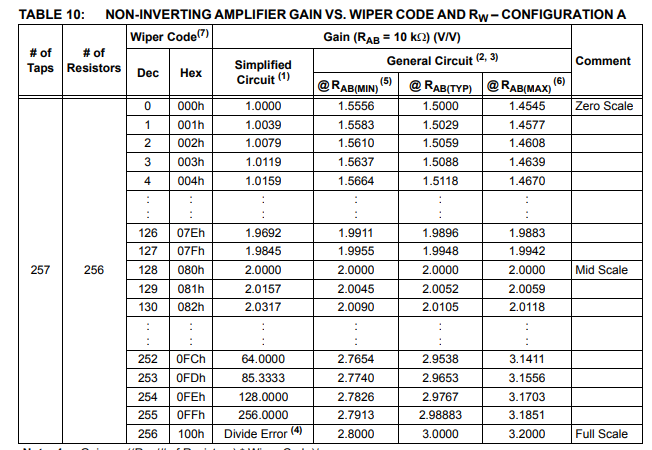
Half of the wiper codes map to closed loop gains between 1 and 2. There isn’t a lot of choice for larger gains after a gain of 64 then next available choice is 128.

Pretty Neat! I don’t happen to need more than 20 kHz of bandwidth, so finding an op-amp with a gain-bandwidth product greater than 20kHz*128 = 2.6 MHz is not a problem.
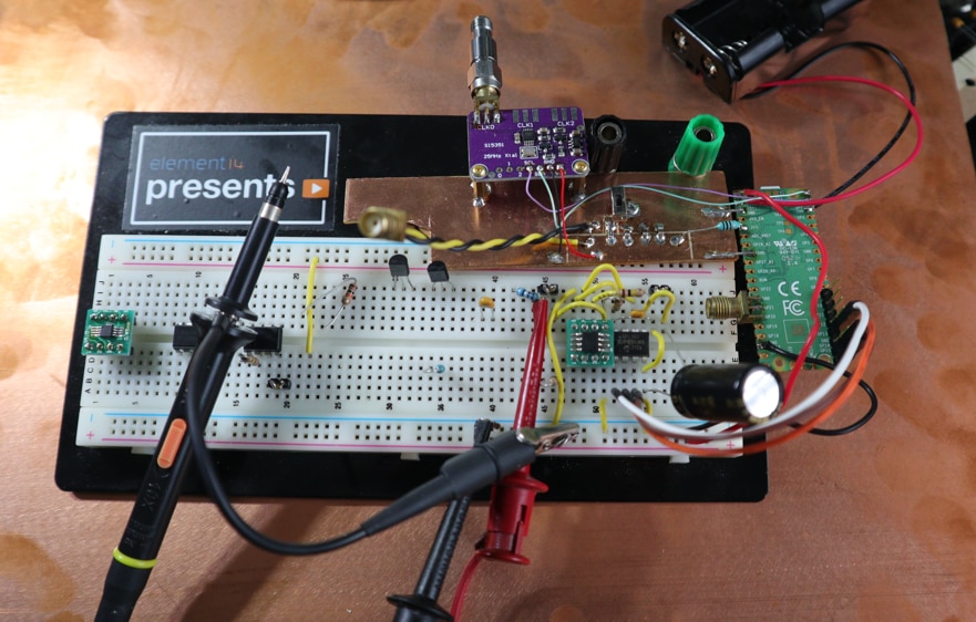
Breadboard

It just so happens I have some digital potentiometers laying around.
Specifically, the Microchip MCP4131 digital POT, which has 7-bit resolution and a total ladder resistance of 10k.

https://ww1.microchip.com/downloads/aemDocuments/documents/OTH/ProductDocuments/DataSheets/22060b.pdf

I also have some Renesas ISL28291 dual-opamps.

Both have been sent to me by element14 (and the cool breadbroad, thanks element14!)

I tossed them onto a breadboard and used a RPI pico to interface with the MCP4131 (github.com/.../main)

image


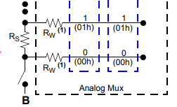
Just like a rotary potentiometer the digiPOT has 3 terminals: A, B, W

image

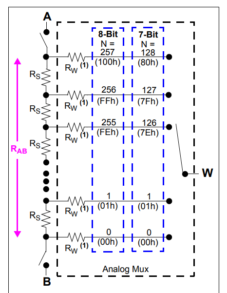
Instead of a having a continuous resistance track and a movable wiper contact, the digi pot has 128 small resistors in a series string and an analog mux that can select any of the 129 tap points.

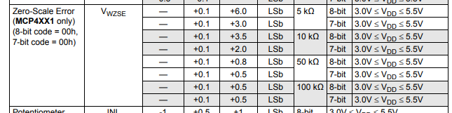
If you apply a fixed potential across the A and B terminals, then with the wiper to set to mid-scale code, the output voltage is half the input. At a wiper code of 0, ideally the wiper voltage should be 0 (unfortunately due to the resistance of the terminal disconnect switch it slightly greater than 0).

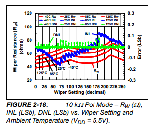
User beware, behavior at the extreme tap-points is worse than advertised.

At a wiper code of 127, I measured a gain of 80x instead of the ideal value of 128x. Disappointing.

There also isn’t a lot of ‘gain resolution’, the previous wiper code of 126 provides an ideal gain of 64x.

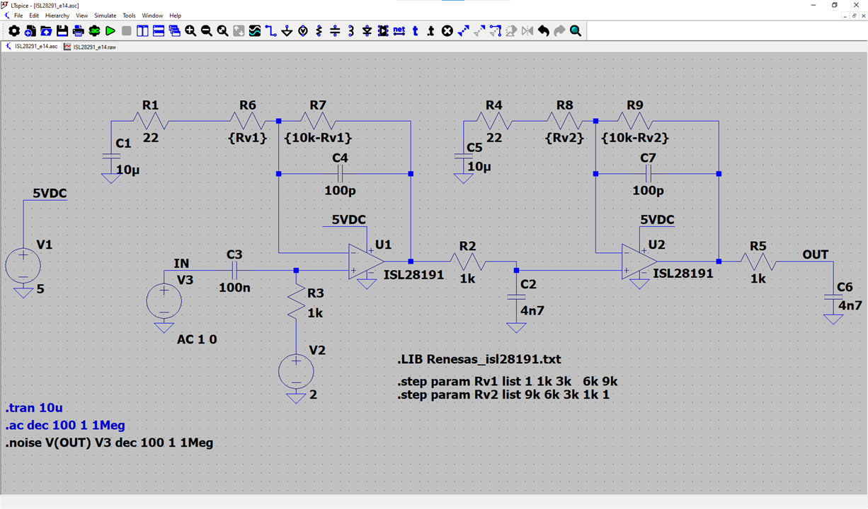
Compounding 2 for more gain and resolution

To achieve a higher total gain and have more gain steps to choose from, I put 2 in series.

image

Now with 2 stages, there are 5363 unique gain values.

image

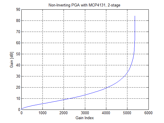
The vast majority of the unique gains are below 50 dB. Above 50 dB there are 55 unique gain values.

Here is a scopeshot of the PGA cycling between a gain of 1 and 6

image

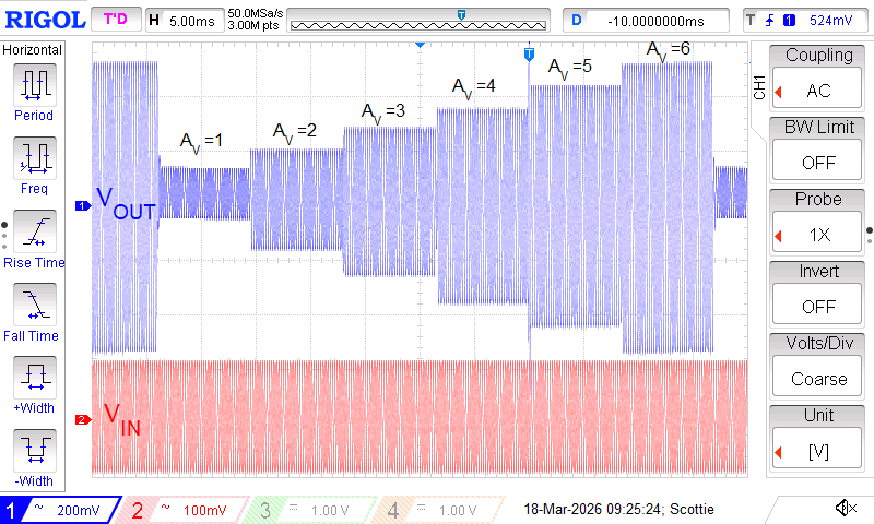
The brief excursion on the scope plot is python being slow, micropython takes its sweet time between the spi write of the first and second digiPOT.

image

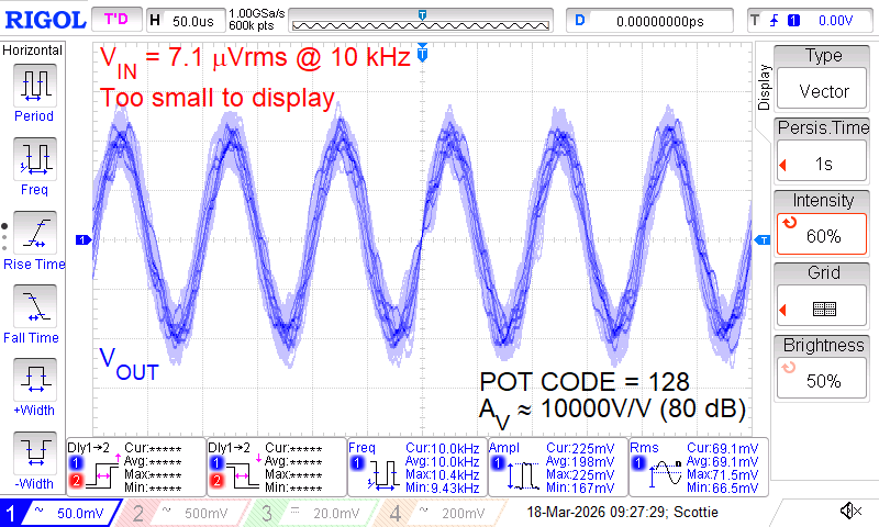
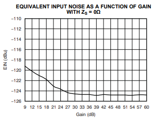
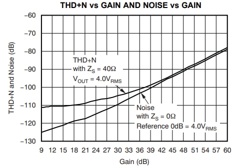
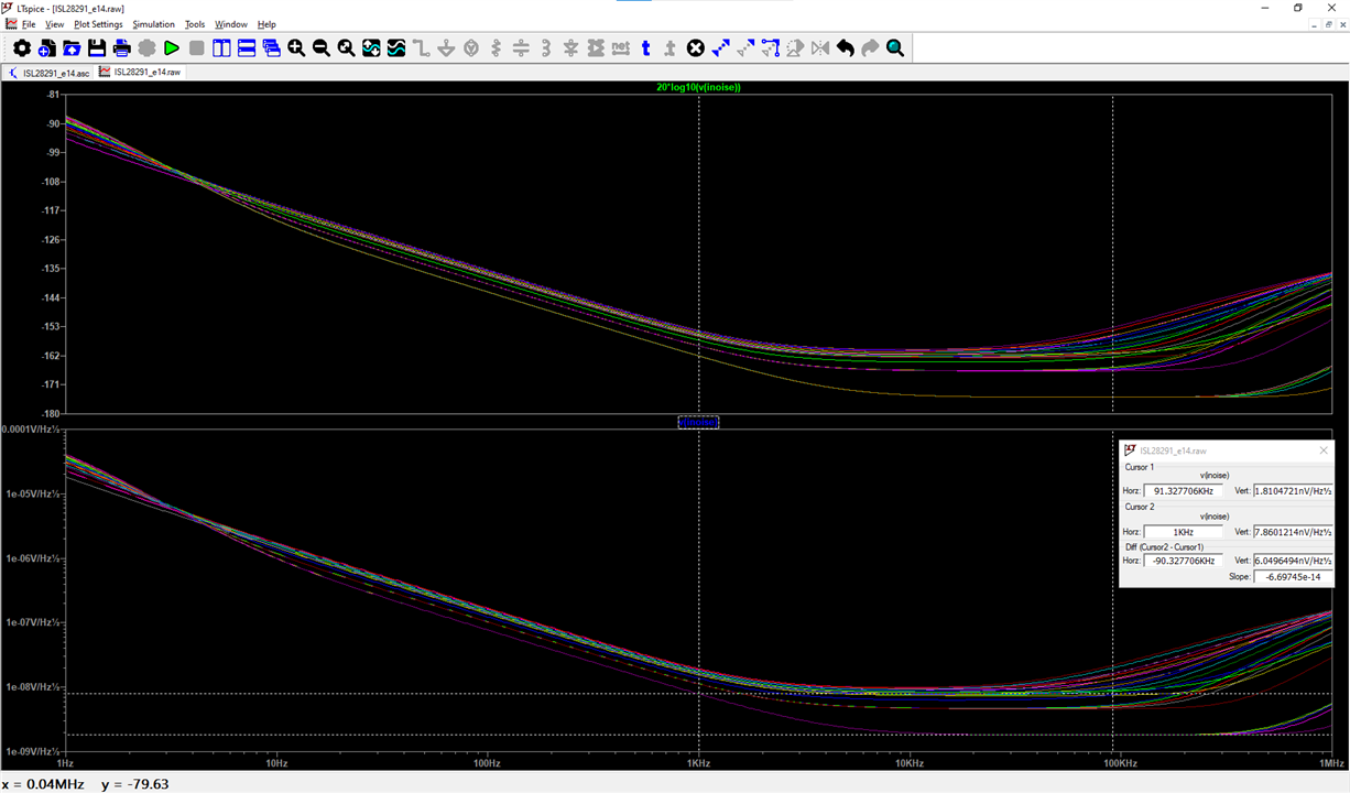
In summary, I am pretty happy with the dynamic range of the amplifier. The amplifier can be programed to provide gains of anywhere between unity and 10000x with 20 kHz of bandwidth and an input referred noise of approximately 3nV/rootHz.

Not bad for parts I had laying around. All the big name semi’s have PGAs with lower noise and more bandwidth all integrated within a single IC for reasonable prices. So, if you need one, you can shop around for a pre-engineered solution. 

  • Sign in to reply
  • Cancel

Top Replies

  • dang74
    dang74 2 days ago +4
    scottiebabe said: At a wiper code of 127, I measured a gain of 80x instead of the ideal value of 128x. Disappointing. Well on the bright side, for that one setting you made a decimal to hexadecimal converter…
  • michaelkellett
    michaelkellett 2 days ago +3
    For reasonable performance the amplifier needs a GBw product greater than 5 x max gain after feedback x working bandwidth. Your ISL29291s are fine (having Gbw of 60Mhz.). I'm impressed how well it works…
  • wolfgangfriedrich
    wolfgangfriedrich 1 day ago +2
    I am very interested in ultra-low noise opamps. I might plug this circuit into LTspice to see if the INOISE really lands close to 3nV/rtHz.
  • michaelkellett
    michaelkellett 2 days ago

    For reasonable performance the amplifier needs a GBw product greater than 5 x max gain after feedback x working bandwidth. Your ISL29291s are fine (having Gbw of 60Mhz.).

    I'm impressed how well it works, considering the low cost Microchip digital pots you used. Did you try measuring the frequency response at high gains ?

    MK

    • Cancel
    • Vote Up +3 Vote Down
    • Sign in to reply
    • Cancel
  • DAB
    DAB 2 days ago

    Nice post.

    • Cancel
    • Vote Up +1 Vote Down
    • Sign in to reply
    • Cancel
  • dang74
    dang74 2 days ago
    scottiebabe said:
    At a wiper code of 127, I measured a gain of 80x instead of the ideal value of 128x. Disappointing.

    Well on the bright side, for that one setting you made a decimal to hexadecimal converter.... 128 being 0x80 in hex.  Wink 

    • Cancel
    • Vote Up +4 Vote Down
    • Sign in to reply
    • Cancel
  • SensoredHacker0
    SensoredHacker0 2 days ago

    7bit gtfo these things are all ladder adders, 
    https://datasheet.octopart.com/AD5206BRU10-Analog-Devices-datasheet-8405.pdf

    you'd be better with a programmable instrumentation amplifier, the results would be cleaner with less step chatter.

    the ladder pots are all subject to variation, you might get 10 bits precision, but youll never get 2 programmable pots that behave exactly the same.  which might be why we dont see these things in more prolific use. 

    • Cancel
    • Vote Up +1 Vote Down
    • Sign in to reply
    • Cancel
  • scottiebabe
    scottiebabe 1 day ago in reply to michaelkellett

    Great advise, I could have expanded more on GBW product. 

    At maximum gain the upper -3db point is still largely determined by the RC low pass filters(luckily the op-amps are plenty fast)

    Here is a frequency sweep (sorry my o-scope doesn't have social media upload to tik-tok buttons, so a cheesy video instead)

    You don't have permission to edit metadata of this video.
    Edit media
    x
    image
    Upload Preview
    image

    *There is an inline 50 dB PAD before the DUT, so the input is 30 uVrms 

    Blue: Input before PAD

    Yellow: DUT Output

    • Cancel
    • Vote Up 0 Vote Down
    • Sign in to reply
    • Cancel
  • scottiebabe
    scottiebabe 1 day ago in reply to dang74

    Very clever observation!

    They post fancy INL/DNL graphs, which in general are accurate except for the very last couple tap points

    image

    The first few and last few codes are worse.

    image

    I guesstimate the end terminal switch had about 1/2 RS of resistance. So instead of a gain of 1+ 127/1, it was closer to 1+127/1.5

    Buried in datasheet, the zero-code offset error could be up to 2 LSB

    image

    • Cancel
    • Vote Up +1 Vote Down
    • Sign in to reply
    • Cancel
  • michaelkellett
    michaelkellett 1 day ago in reply to scottiebabe
    scottiebabe said:

    I guesstimate the end terminal switch had about 1/2 RS of resistance. So instead of a gain of 1+ 127/1, it was closer to 1+127/1.5

    Buried in datasheet, the zero-code offset error could be up to 2 LSB

    The 22R resistor will make this worse (but it does give you some control of the gain if you select the 'zero' position of the wiper.

    MK

    • Cancel
    • Vote Up +1 Vote Down
    • Sign in to reply
    • Cancel
  • scottiebabe
    scottiebabe 1 day ago in reply to SensoredHacker0

    The op-amp I used has an average PSRR/CMR, so while the op-amp may reject power supply noise by 60 - 70 dB, at the maximum gain setting it gets amplified back up. Instrumentations amps generally have much better specs in that regard.

    You may used fixed gain amps with attenuators, or step attenuators in the feedback path, or pre-engineered parts. 

    • Cancel
    • Vote Up 0 Vote Down
    • Sign in to reply
    • Cancel
  • scottiebabe
    scottiebabe 1 day ago in reply to michaelkellett

    That's why I included it, so I can use wiper code 128 as a try and see, for the parts I had used it allows for a gain setting over 100x but not much more

    • Cancel
    • Vote Up 0 Vote Down
    • Sign in to reply
    • Cancel
  • wolfgangfriedrich
    wolfgangfriedrich 1 day ago

    I am very interested in ultra-low noise opamps. I might plug this circuit into LTspice to see if the INOISE really lands close to 3nV/rtHz.

    • Cancel
    • Vote Up +2 Vote Down
    • Sign in to reply
    • Cancel
>
element14 Community

element14 is the first online community specifically for engineers. Connect with your peers and get expert answers to your questions.

  • Members
  • Learn
  • Technologies
  • Challenges & Projects
  • Products
  • Store
  • About Us
  • Feedback & Support
  • FAQs
  • Terms of Use
  • Privacy Policy
  • Legal and Copyright Notices
  • Sitemap
  • Cookies

An Avnet Company © 2026 Premier Farnell Limited. All Rights Reserved.

Premier Farnell Ltd, registered in England and Wales (no 00876412), registered office: Farnell House, Forge Lane, Leeds LS12 2NE.

ICP 备案号 10220084.

Follow element14

  • X
  • Facebook
  • linkedin
  • YouTube