


As mentioned in the Azure Sphere Secure IOT - First look the next step is to "claim" the board. This registers the device with the portal so you can remote control it.
Login
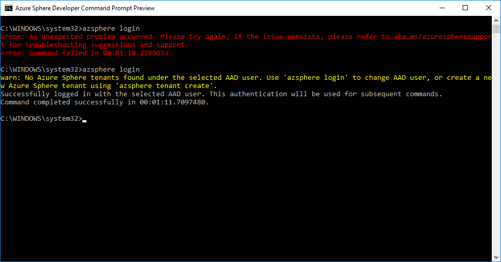
One of the things installed with the dev kit is the Azure Sphere Developer Command Prompt. This is just a console window where you can type the azsphere commands necessary to setup the kit. To login you use:
azsphere login
The documentation states that you need to have a work or school account. However, I found that my Azure login did have the correct permission but I did have Azure Active Directory enabled on my portal.
Looking under Azure Active Directory and Custom domain names, you should the name there which was the "Organisation" name you entered when you first setup the Azure account. It should look a bit like the following.
| NAME | STATUS | FEDERATED | PRIMARY |
|---|---|---|---|
| myorganisation | Available |  |
Then follow the instructions at create-a-new-account-and-directory to create a test user @myorganisation.onmicrosoft.com
You should then be able to login with that new account.
Creating a device
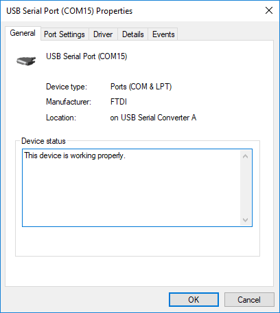
You'll need the board plugged in for this step. I plugged mine in and 3 serial ports were created using an FTDI driver. See Azure Sphere Secure IOT - A closer look
As mentioned claiming the device for a tenant is an irreversible step. I've scrubbed the IDs as I don't know of the security connotations of sharing those.
https://docs.microsoft.com/en-us/azure-sphere/install/claim-device

Once you've your board claimed the next step is setting up the Wifi. This can be done with
azsphere device wifi show-status
and
azsphere device wifi add --ssid My5GNetwork --key secretnetworkkey
And once you've got it on wifi you can check that it has the lastest OS version. Mine's currently on the technical preview 4.2.1 https://docs.microsoft.com/en-us/azure-sphere/resources/release-notes-421

Hello World
For those who use dev boards a lot you'll know that the "hello world" of dev boards is "blink" and it's no different here. The Azure Sphere is no different although their demo does include some buttons as well as flashing LEDs.
The code is fairly readable but there does seem to be quite a lot going on compared to a simpler board. There's also a lot of error handling around the handling of resources such as the GPIO etc so it's good to know how that works.
One thing that's in all of the examples is a termination handler. Those who've written code for Linux should be familiar with this and I've seen it in many python scripts. The idea is that when there's an over the air update the application can be alerted and properly shut down, save state etc before the OTA takes over and applies the update.
Like an interrupt handler the code in the actual handler is very simple, it just toggles a flag.
// Termination state
static volatile sig_atomic_t terminationRequired = false;

/// <summary>
///     Signal handler for termination requests. This handler must be async-signal-safe.
/// </summary>
static void TerminationHandler(int signalNumber)
{
    // Don't use Log_Debug here, as it is not guaranteed to be async signal safe
    terminationRequired = true;
}
Then in the main loop (which you have to code yourself, see line 13) there's a check for this variable and the code exits if it's been set to true.
/// <summary>
///     Main entry point for this application.
/// </summary>
int main(int argc, char *argv[])
{
    Log_Debug("Blink application starting\n");
    if (InitPeripheralsAndHandlers() != 0) {
        terminationRequired = true;
    }


    // Use epoll to wait for events and trigger handlers, until an error or SIGTERM happens
    while (!terminationRequired) {
        if (WaitForEventAndCallHandler(epollFd) != 0) {
            terminationRequired = true;
        }
    }


    ClosePeripheralsAndHandlers();
    Log_Debug("Application exiting\n");
    return 0;
}
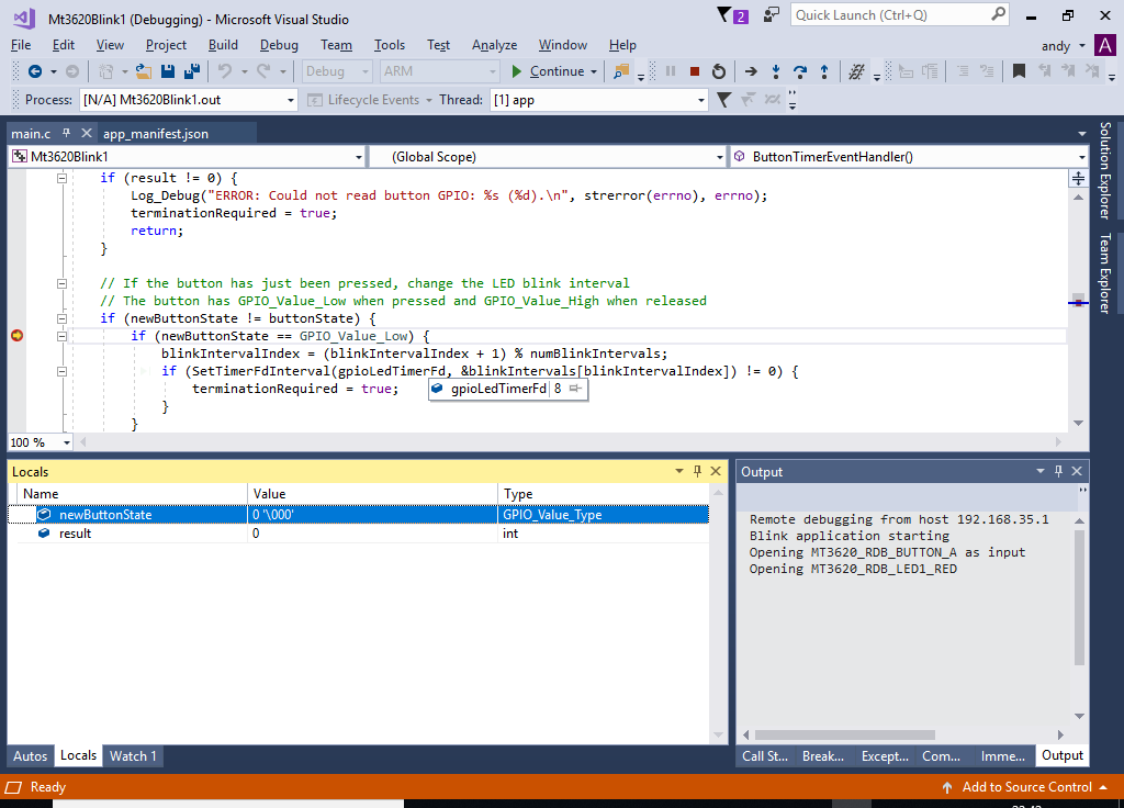
Note that stopping the debugger does not trigger this check but you can add a breakpoint to line 14 above (182 in the example) then simply change the line of code that's executing by dragging the yellow program counter pointer down to line 15. Then the app will go through it's proper shutdown.
Upload
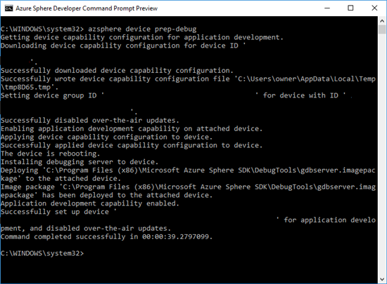
The usual process for getting code onto the device is via the over the air updates. That's a bit arduous so you can "sideload" it from your PC, but you need to add the "capability" to the device to do that. That is done with the prep-debug command. You can remove this capability for your deployed solution.
https://docs.microsoft.com/en-us/azure-sphere/reference/azsphere-device#capability-cap
You can upload your code from the Visual Studio IDE just by running the debugger or console
The next thing in the online guide is looking at the deployment processes. Whilst reading up on that I'm going to attach some real hardware to the GPIO pins and UART.
Overview Video
Here's another overview of the board and a demo, I spotted.
https://channel9.msdn.com/Events/Build/2018/BRK3801

