


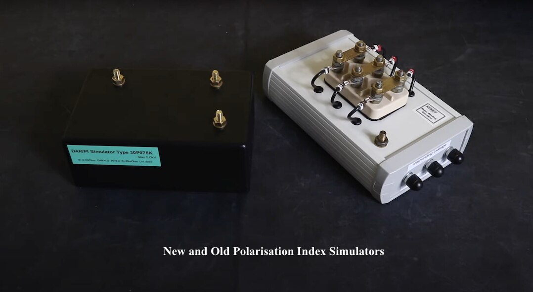
Those who have read some of my insulation tester reviews may remember that I have a 3 phase polarisation index simulator, that I utilise for one of the bench marking tests I carry out. This provides a consistent test bed, that should produce a comparable result, irrespective of the test environment or the insulation tester utilised. As I have used it though, I have come to realise a few drawbacks of the unit.
Modifying my Motor Winding Simulator
The first is that it has a test voltage limit of 500V, and is therefore not suitable for a number of the insulation testers I have at my disposal.
The second, is its relatively low insulation test value does not test out the extended range of insulation resistance capability of a lot of the modern insulation testers.
The third is that due to its highly capacitive nature, it retains a charge for quite some time after the test and this can interfere with the operation of some insulation testers.
In this blog, I am gong to try and address these issues with a new design for the PI simulator. I will however restrict this to a single phase solution. I also aim to take a deeper look at the theory behind the simulator to produce a theoretical model for comparison to the readings taken.
If you prefer a video format, the video below is around 13 minutes long and goes into the design, build and test, but pretty much contains the same information as the blog below.
The simulators are a basic RC network with an extended charging time to compensate for the 10 minute polarisation index test. Whilst a lot of insulation testers have a limited capability of around 500 MOhms for a 500 V test, they often have a capability more towards 20 GOhms when testing at 1000 V. This gives me a starting point for selecting the end resistance value, that I decided to be in the region of 15 GOhms. A rummage around through my high voltage resistor box, provides me with two 5 GOhm and one 3 GOhm resistor. Put in series this gives me 13 GOhms.
Prior to creating theoretical models for the PI simulator I used to base the rest of my component sizing on a resistance ratio in-between 10 to 15 to give me the second resistance value and then a time constant between 80 to 120 to give me the required capacitance value. This gives me a value for the other resistor of 860 MOhm to 1.3 GOhm. I have available to me, 300 MOhm, 500 MOhm and 1 GOhm resistors, so have a number of combinations to work with.
I can rearrange the standard time constant formula to provide me with a trial capacitor value for the circuit.
t = C x R, therefore C = t / R
nominally set t to 100, therefore C = 100 / 1,000,000,000
Trial capacitor C = 100 nF
Voltage wise, the capacitor will have to be rated at, or preferably above, the test voltage applied by the insulation tester. Since I do not have a capacitor with a 5000V rating, initial tests are done at lower voltages and I can then purchase the desired sized capacitor with the correct voltage rating.
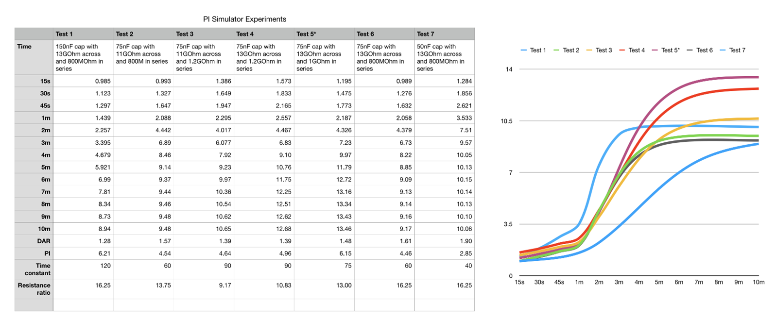
Fine tuning was then a process of setting up an experiment on a bench with a box of components at the ready, and an insulation tester. Giving that each experiment has to be 10 minutes long to capture the polarisation index curve, this can be quite a lengthy test period.
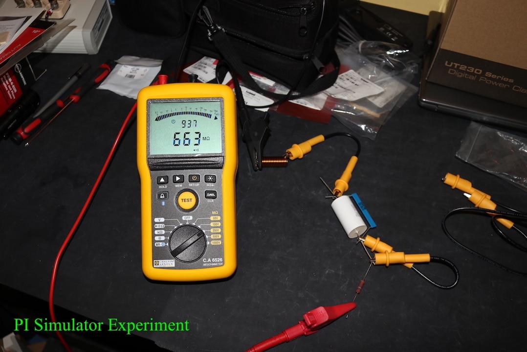
Looking at the test figures produced from some of the experiments, those values would never match the time constant calculations based upon the R2 and C1 values. This is because the circuit is actually a little more complicated as the R1 value affects the current seen by the capacitor. So to solve this circuit I need a bit of Thevenin's Theorem to break the complex circuit down into a simple one.
The objective of Thevenin's Theorem is to simplify the circuit to a single equivalent source and one series resistance for the load. In my case, this will provide a more accurate time constant calculation for the capacitor. I will not go into Thevenin's Theorem here as there are plenty of resources available on the internet, some of which are;
All About Circuits Thevenin's Theorem blog
Wikipedia Thevenin's Theorem
We start off with the original circuit consisting of the inductor L1, the capacitor C1, in parallel with resistor R1, with this combination in series with resistor R2. For this circuit, the load is considered as C1 and is therefore removed from the circuit. As the inductor is such low resistance, it can also be removed from the circuit. This leaves me with the insulation tester providing the test voltage across R1 and R2.
The equivalent Thevenin voltage will be the voltage across R1, which will ultimately be the voltage across the load C1, when it is in circuit. We can calculate this voltage using Ohms theory.
Current flowing I = Test voltage / (R1 + R2)
I = 5000 / 14,000,000,000
I = 357 nA
Calculate Thevenin Voltage
V = R1 x I
V = 13,000,000,000 x 0.000000357
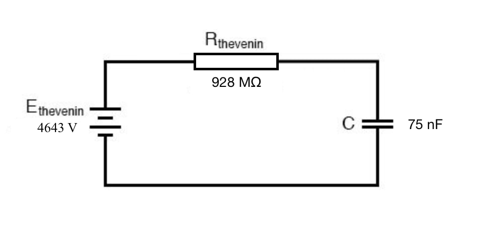
V = 4643 V
I now work out the equivalent Thevenin Resistance using this voltage and the circuit resistances. The supply from the insulation tester is removed and shorted out. This means that in relation to the Thevenin Voltage, the two resistance are now seen as being in parallel.
Rt = 1 / ( (1 / R1) + (1 / R2) )
Rt = 1 / ( (1 / 13,000,000,000) + (1 / 1,000,000,000) )
Rt = 1 / 0.00000000010769
Rt = 928.571 MOhms
This leaves me with a final equivalent circuit looking like this;
From this I can now calculate the charge on the capacitor at any specific point in time using the formula below;
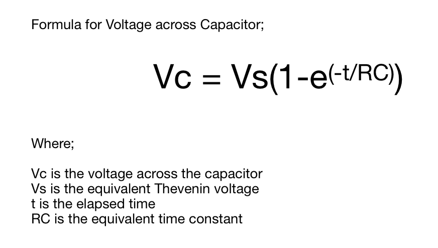
This allows me to calculate the current that would be flowing from the insulation tester, and hence the insulation reading it would be displaying. This is easier done in a spreadsheet.
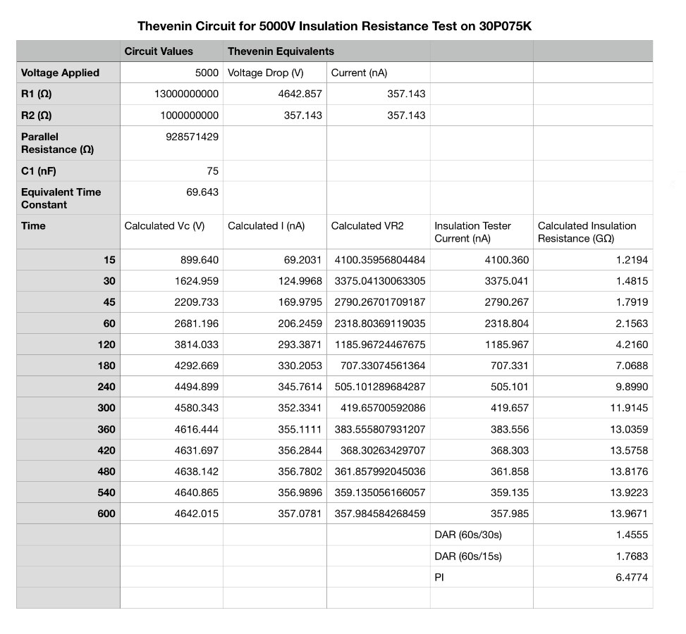
This gives me a further advantage, that I can now also see the voltage across the components, to ensure that they are suitably rated. There are a couple of further options of the table. I can add in th tolerances for the components, so that I can create an expected minimum and maximum resistance curves, so my actual curve should then hopefully lie between the two. Alternatively, I could measure the components and insert the measured values in place of the nominal component values.
As I want to go up to 5000V test voltage, this will limit my selection of the resistors to specific high voltage items, one of my favourites to utilise are the Slim-Mox 10403 series from Ohmite. These are available in a limited resistance values, so usually the resistor has to be made up from adding together a number of resistors.
Ohmite Slim-Mox range at Farnell
For the capacitors, it can sometimes be awkward to find the required capacitance value with the right voltage level, so the possibility of parallel / serial combinations can be explored. Browsing the polypropylene range revealed a 0.15 uF capacitor rated at 3 kV. Two of these in series will half the capacitance, down to the desired 75 nF and double the voltage to 6 kV, which will exceed the test voltage rating I want for my simulator.
To put this all together, I need a few more pieces;
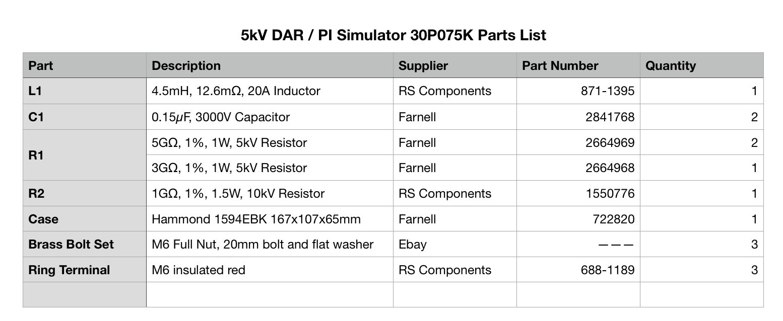
The inductor I had lying around, so decided to put it to use as it adds another test dimension to the simulator. It doesn't have to be an inductor, a low value resistor could be utilised, or it could be left out of the circuit completely. Likewise, brass, bolts do not have to be used for the connections, standard steel bolts or 4mm test sockets or binding posts are also options. However, for the voltage level I am going to, the brass bolts seem like a good option.
This is what it all looks like put together in the case;
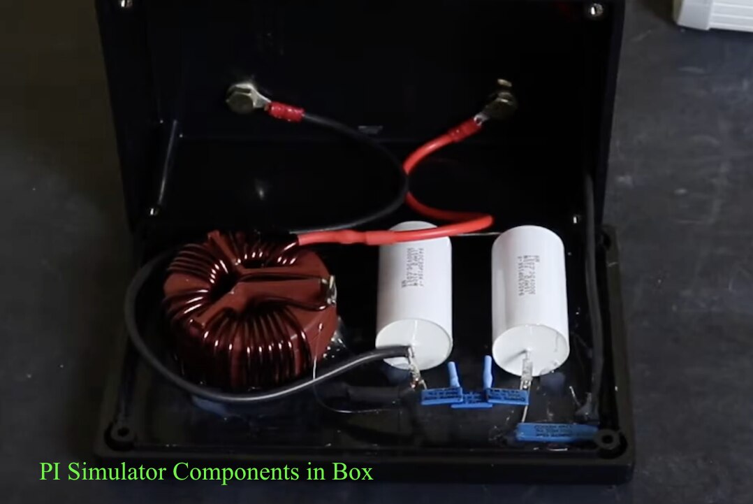
I space the components out inside to try and avoid leakage currents from the high voltage that will be applied to it. I put heat shrink around as many of the connections as I can and the internal wiring is made from silicone test lead. The components are held in place with hot glue, I roughed up the internal surfaces of the box with sandpaper to improve the adhesion.
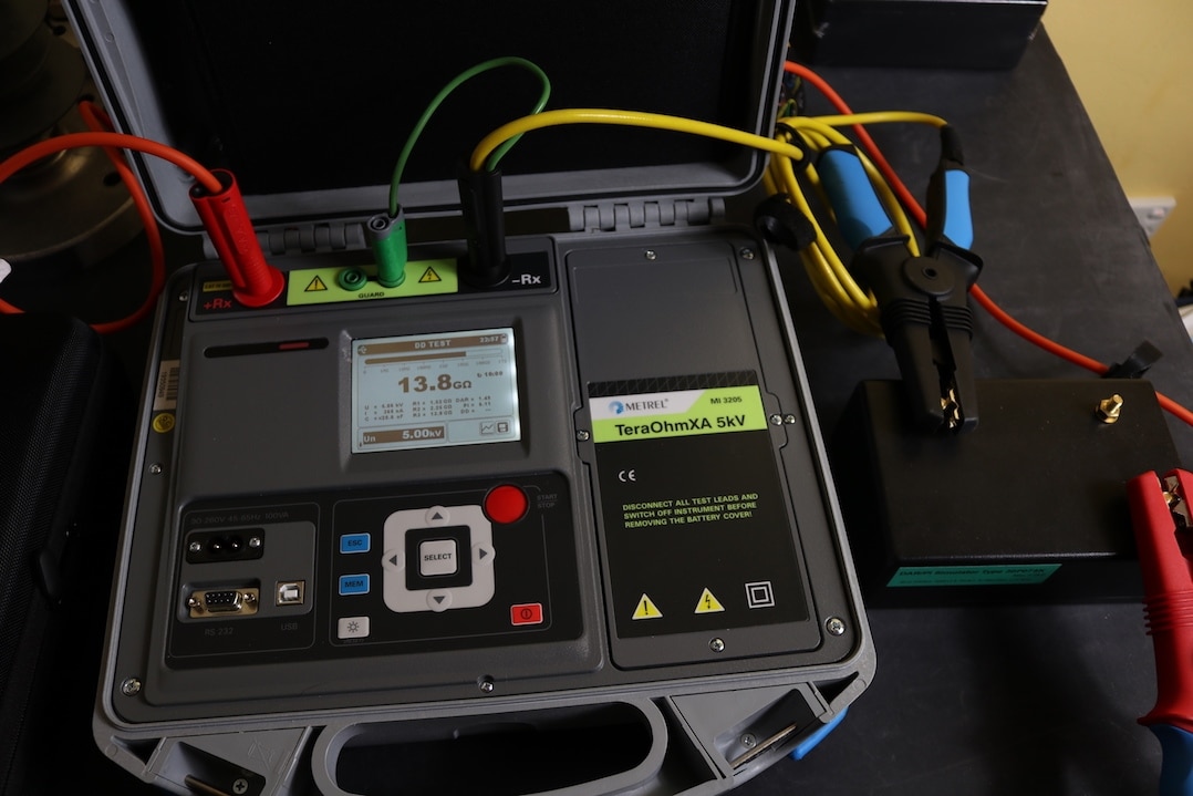
Time for testing, no point in messing around, so lets go for 5000V, supplied by the Metrel MI3205 insulation tester
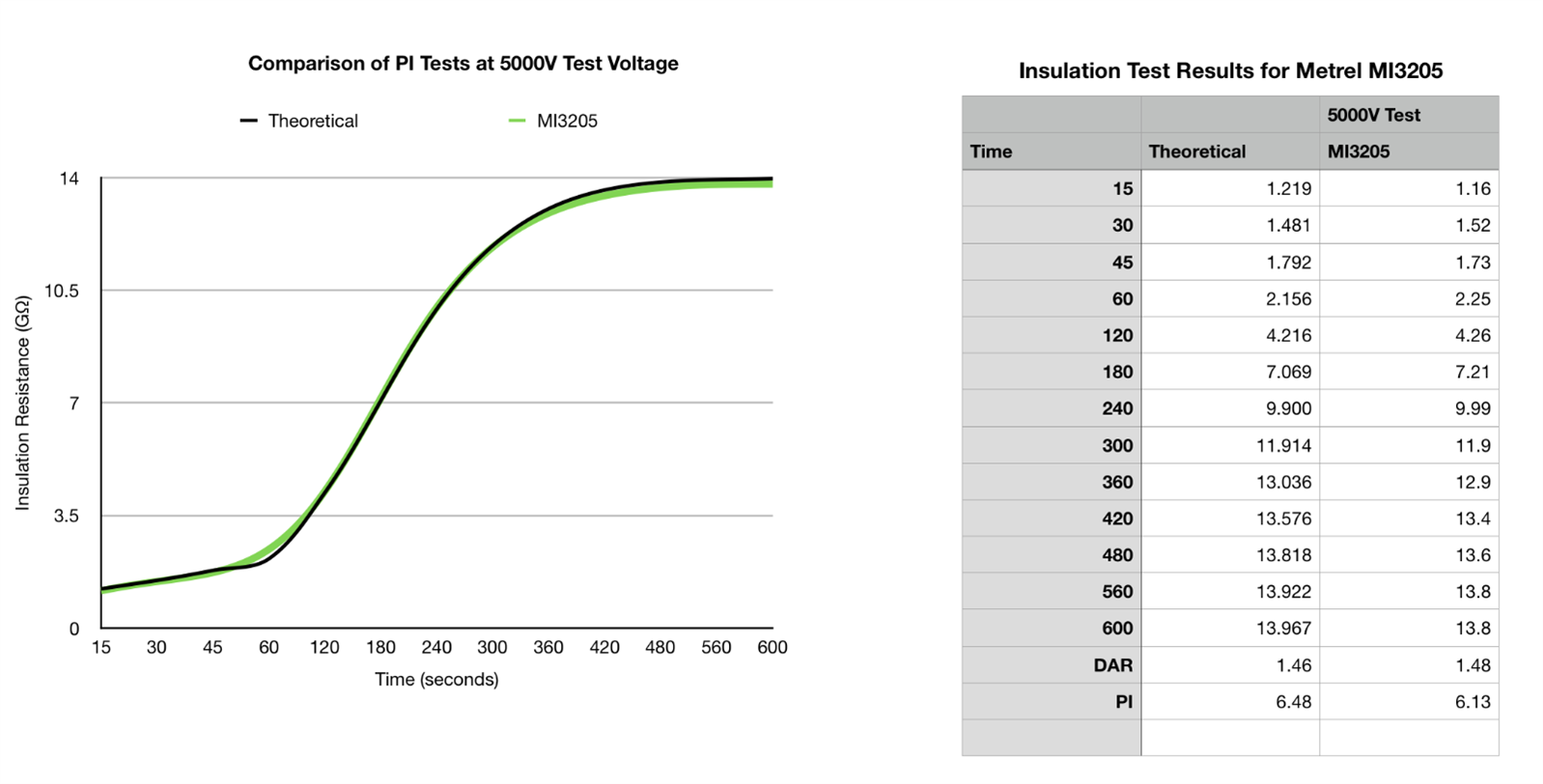
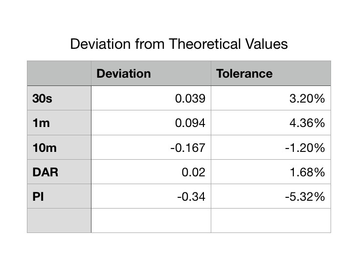
This seems to be a perfectly acceptable set of results for the simulator. The most variation is seen at the 1 minute reading where the actual reading was 4.36% above the expected value. This has consequentially led to the difference in the DAR and PI values. The output plot shows a good correlation of the lowest and highest test voltages against the mathematically derived curve, which is particularly pleasing.
I also have the Fluke 1555 at my disposal. I tested the simulator at 5 different test voltages that the 1555 is capable of. As with all the polarisation index tests I carry out, I took readings at 15 seconds for the first minute and at every minute after that so that I can plot the insulation resistance values.
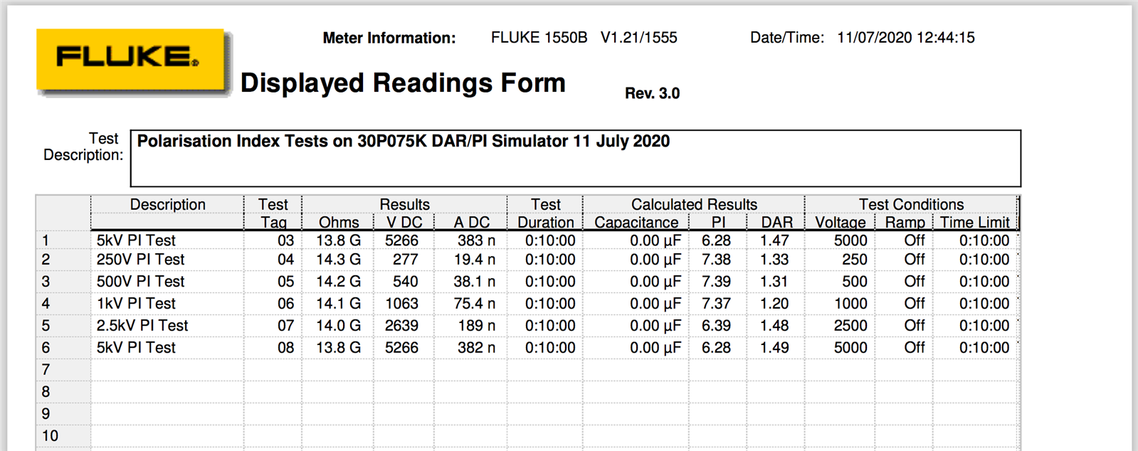
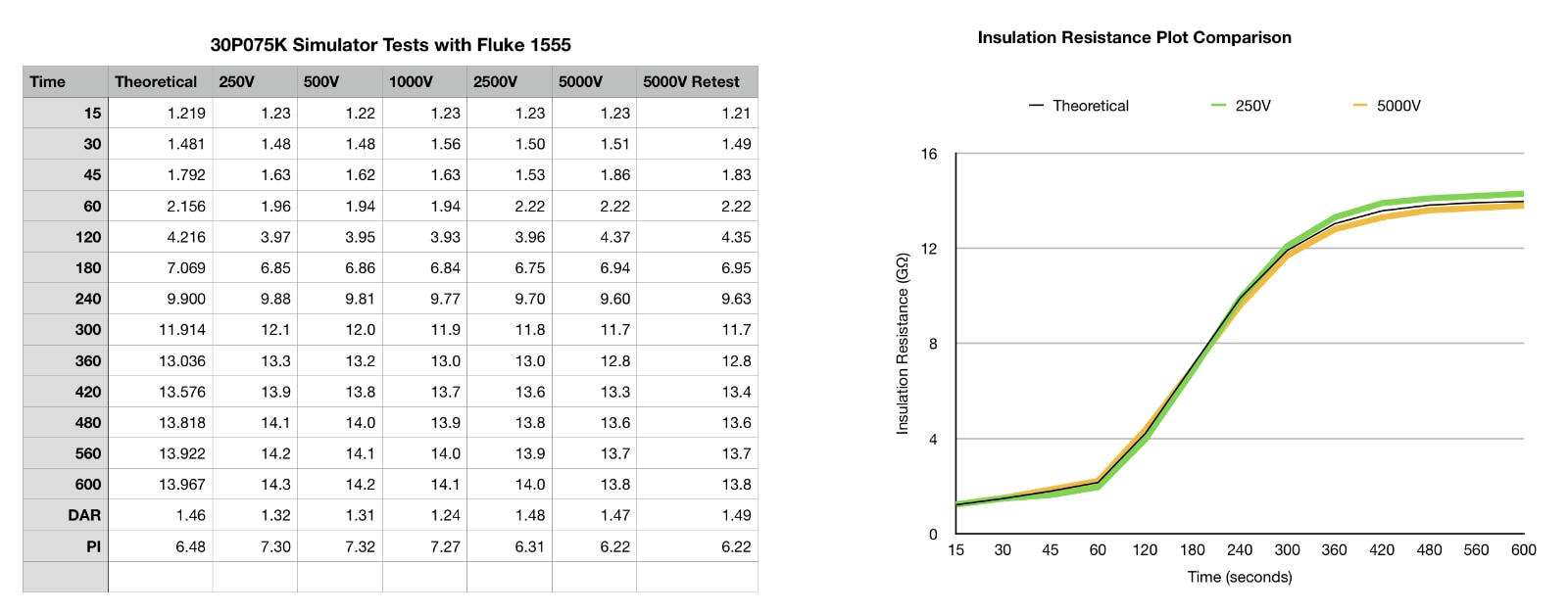
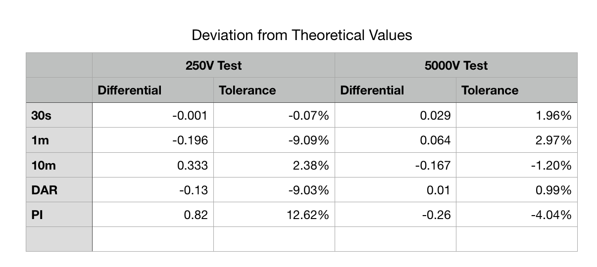
The output plot shows the lowest and highest test voltages against the mathematically derived curve. A higher difference is seen for the 250V test on this tester than for the Metrel unit, but the 5000V test results are a little better.
Overall, this is a pleasing set of results. Being able to test the DAR and PI functionality of an insulation tester has always been a good option for me, but I have now succeeded in extending this capability to be able to match the performance of an insulation tester to a theoretical model. It is also good to extend the voltage capability of the simulator, so that different ranges of the instruments can be tested, instead of sticking to the lower voltages.
This now opens up more avenues for me to build some simulators with different DAR and PI ratios over different insulation values, so that similar tests can be carried out on other insulation testers.
Top Comments