element14 Community
element14 Community
    Register Log In
  • Site
  • Search
  • Log In Register
  • Community Hub
    Community Hub
    • What's New on element14
    • Feedback and Support
    • Benefits of Membership
    • Personal Blogs
    • Members Area
    • Achievement Levels
  • Learn
    Learn
    • Ask an Expert
    • eBooks
    • element14 presents
    • Learning Center
    • Tech Spotlight
    • STEM Academy
    • Webinars, Training and Events
    • Learning Groups
  • Technologies
    Technologies
    • 3D Printing
    • FPGA
    • Industrial Automation
    • Internet of Things
    • Power & Energy
    • Sensors
    • Technology Groups
  • Challenges & Projects
    Challenges & Projects
    • Design Challenges
    • element14 presents Projects
    • Project14
    • Arduino Projects
    • Raspberry Pi Projects
    • Project Groups
  • Products
    Products
    • Arduino
    • Avnet Boards Community
    • Dev Tools
    • Manufacturers
    • Multicomp Pro
    • Product Groups
    • Raspberry Pi
    • RoadTests & Reviews
  • Store
    Store
    • Visit Your Store
    • Choose another store...
      • Europe
      •  Austria (German)
      •  Belgium (Dutch, French)
      •  Bulgaria (Bulgarian)
      •  Czech Republic (Czech)
      •  Denmark (Danish)
      •  Estonia (Estonian)
      •  Finland (Finnish)
      •  France (French)
      •  Germany (German)
      •  Hungary (Hungarian)
      •  Ireland
      •  Israel
      •  Italy (Italian)
      •  Latvia (Latvian)
      •  
      •  Lithuania (Lithuanian)
      •  Netherlands (Dutch)
      •  Norway (Norwegian)
      •  Poland (Polish)
      •  Portugal (Portuguese)
      •  Romania (Romanian)
      •  Russia (Russian)
      •  Slovakia (Slovak)
      •  Slovenia (Slovenian)
      •  Spain (Spanish)
      •  Sweden (Swedish)
      •  Switzerland(German, French)
      •  Turkey (Turkish)
      •  United Kingdom
      • Asia Pacific
      •  Australia
      •  China
      •  Hong Kong
      •  India
      •  Korea (Korean)
      •  Malaysia
      •  New Zealand
      •  Philippines
      •  Singapore
      •  Taiwan
      •  Thailand (Thai)
      • Americas
      •  Brazil (Portuguese)
      •  Canada
      •  Mexico (Spanish)
      •  United States
      Can't find the country/region you're looking for? Visit our export site or find a local distributor.
  • Translate
  • Profile
  • Settings
Personal Blogs
  • Community Hub
  • More
Personal Blogs
Legacy Personal Blogs 555cc
  • Blog
  • Documents
  • Mentions
  • Sub-Groups
  • Tags
  • More
  • Cancel
  • New
  • Share
  • More
  • Cancel
Group Actions
  • Group RSS
  • More
  • Cancel
Engagement
  • Author Author: jc2048
  • Date Created: 9 Jul 2018 1:46 PM Date Created
  • Views 5287 views
  • Likes 14 likes
  • Comments 6 comments
  • transistor
  • constant current
  • 555 timer
  • triangle wave
  • circuit design
Related
Recommended

555cc

jc2048
jc2048
9 Jul 2018

This is some more experimenting and general 'fiddling around' sparked off by the Project14 Simple Music Maker challenge.


555 timers have been around for a long time. When the UK electronics store chain Maplin went out of business a couple of

months ago, amongst the devices that I bought in their closing down sale were some 555s. I was curious to see if I could get

a 555 timer producing a reasonable triangle waveform and that's the subject of this blog. It's not a project. It's not an

example of 'good' design. It's not even of much consequence other than perhaps an encouragement to experiment and go beyond

the standard circuits given on datasheets.


Here's the circuit I came up with.


image


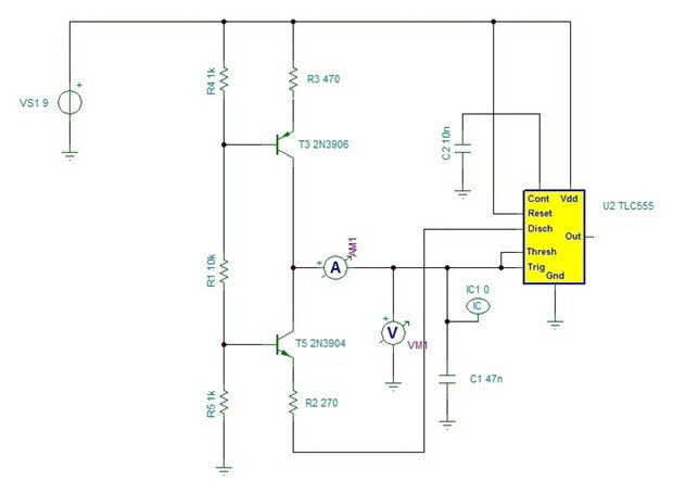
This has a pair of current sources. The high one (T3) sources half the current that the lower one (T5) sinks. The discharge

pin on the 555 enables the lower one, switching us from a net charging current into the capacitor to a similar sized

discharging current out of it. That should produce a linear ramp up and down. The frequency is dependent on the current,

which is set by R1 and the mark/space ratio should remain fairly constant with frequency as the change in current will

scale the bottom current in a roughly similar proportion to the top current (only roughly because of the offset from the

saturation voltage of the discharge transistor in the 555).


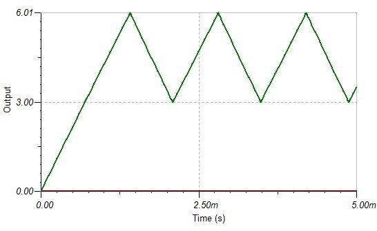
Here are the simulator waveforms. I had to include an initial condition to force the capacitor voltage to 0V at the start -

without it the simulator fails trying to do the dc analysis at the start (something to do with what's going on in the

TLC555 model). The circuit does seem to work and produce a triangle waveform at the capacitor.


image


That's the point I stopped at, originally, when I was doing the Simple Music Maker.


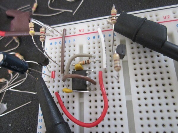
Just to prove it in practice, I've now built it on a breadboard. The 555 I'm using is the standard NE555 part rather than the TLC555 that was all the simulator

had available as a model. (This picture is from a bit later when I'd changed to a 10uF electrolytic for the timing

capacitor - pretend that there's a 47nF ceramic where the electrolytic is.)


image


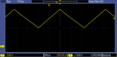
Here is the scope trace of the capacitor voltage.


image


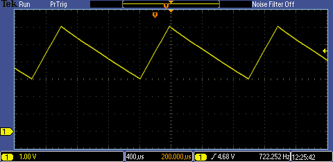
As you can see, the bipolar 555 gives somewhat different results to the simulated CMOS part. If I change R2 to be 180R it

gets closer to the symmetrical sawtooth that I was originally after.


image


Just out of curiosity, I tried substituting a 10uF electrolytic for the 47n to see what it would be like much slower and here is the resulting waveform


image


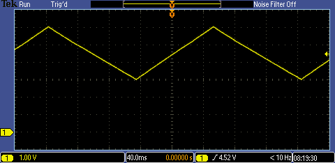
That's something like 5Hz.


We can't load the capacitor voltage too much or it will change the frequency - even the 10M ohm 'scope probe produces a

noticeable change - so to use it in a real circuit you'd need to buffer the capacitor voltage.


That's as much as I want to do with it, so I'll leave it there.

  • Sign in to reply

Top Comments

  • jc2048
    jc2048 over 6 years ago in reply to shabaz +5
    I'm finding that the simulator is really great for experimenting with circuits because it's so fast to try things out. Ideas I wouldn't even try on a breadboard I just slap together quickly and then start…
  • genebren
    genebren over 6 years ago +4
    Hi Jon, Great work on the 555 oscillator. When I was back in school, these little things were the best! I used a bunch of these in a synthesizer project, trying to create a clean multiphonics keyboard…
  • shabaz
    shabaz over 6 years ago +3
    Hi Jon, That's very cool : ) I'd seen sawtooth generation with the 555 before with the top single transistor as current source, but I'd not seen two combined before!
  • kk99
    kk99 over 6 years ago

    Very good example of usage of 555 timer. We need just few components to create useful circuit.

    • Cancel
    • Vote Up +1 Vote Down
    • Sign in to reply
    • More
    • Cancel
  • jw0752
    jw0752 over 6 years ago

    It is really good to play around like this even if a practical application isn't immediately available. It is like practicing as it keeps your skills tuned up and provides resource ideas and experience when an application is present. thank you for sharing your explorations.

    John

    • Cancel
    • Vote Up +2 Vote Down
    • Sign in to reply
    • More
    • Cancel
  • DAB
    DAB over 6 years ago

    I like it.


    Even today the 555 chip still has a wealth of interesting capabilities still waiting to be discovered.


    DAB

    • Cancel
    • Vote Up +2 Vote Down
    • Sign in to reply
    • More
    • Cancel
  • genebren
    genebren over 6 years ago

    Hi Jon,


    Great work on the 555 oscillator.  When I was back in school, these little things were the best!  I used a bunch of these in a synthesizer project, trying to create a clean multiphonics keyboard.  At the time, this was a bit of a reach for my skills, but this might be a fun project to revive some day.


    Gene

    • Cancel
    • Vote Up +4 Vote Down
    • Sign in to reply
    • More
    • Cancel
  • jc2048
    jc2048 over 6 years ago in reply to shabaz

    I'm finding that the simulator is really great for experimenting with circuits because it's so fast to try things out. Ideas I wouldn't even try on a breadboard I just slap together quickly and then start merrily hacking around not having to worry if I'm going to blow anything up.


    This circuit started out a bit different, with a current mirror top and bottom (sharing the current setting resistor), and with a double transistor on the bottom for a x2 current (it wouldn't be all that good as a built circuit, with discrete components, but works nicely in the simulator with identical transistors). But I couldn't figure out a simple way to control it with the discharge output, so changed to this form.


    If you ever wanted to actually use the idea (in practice, you'd use op-amps - slightly more cost, but far more precise control), note that the bottom transistor is a bit on edge when the Disch output isn't pulling the resistor down (I think it's sitting there trying to be a common-base amplifier).

    • Cancel
    • Vote Up +5 Vote Down
    • Sign in to reply
    • More
    • Cancel
>
element14 Community

element14 is the first online community specifically for engineers. Connect with your peers and get expert answers to your questions.

  • Members
  • Learn
  • Technologies
  • Challenges & Projects
  • Products
  • Store
  • About Us
  • Feedback & Support
  • FAQs
  • Terms of Use
  • Privacy Policy
  • Legal and Copyright Notices
  • Sitemap
  • Cookies

An Avnet Company © 2025 Premier Farnell Limited. All Rights Reserved.

Premier Farnell Ltd, registered in England and Wales (no 00876412), registered office: Farnell House, Forge Lane, Leeds LS12 2NE.

ICP 备案号 10220084.

Follow element14

  • X
  • Facebook
  • linkedin
  • YouTube