


In the last couple of weeks I had a little side project: a hamradio dummy load especially for the 2 m and 70 cm hamradio bands but it should also work on higher frequencies. A dummy load (https://en.wikipedia.org/wiki/Dummy_load ) is a handy device when it comes to testing receivers. It is connected to the HF output of the transceiver and burns all the HF energy in a resistor so that no HF signal is transmitted. The dummy load is actually a high power 50 ohm resistor. You only have to take care that parasitic inductance and capacity is low so that it acts as a resistor even at high frequencies. That's why SMD parts are more suitable than THT resistors.

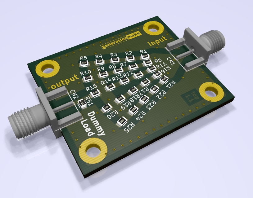
i made my design with KiCad because it allows fast and easy working even when parts are placed in odd angles by using polar coordinates. It also has a nice 3D viewer to check the layout and mechanics of the board. The picture above is a screenshot of this 3D viewer.
The dummy load consists of 51 100 ohm 0805 resistors with a power capacity of 1/8 watts each. That sums up to 6.25 watts for the whole dummy load.
It also has an attenuator output (CN2) with a signal reduction of 20 dB. If this output is not used it has to be terminated with a 50 ohm resistor.
Input and output are connected via a SMA connector so that it easily can connect to the ArduTrx or any other hand held radio.
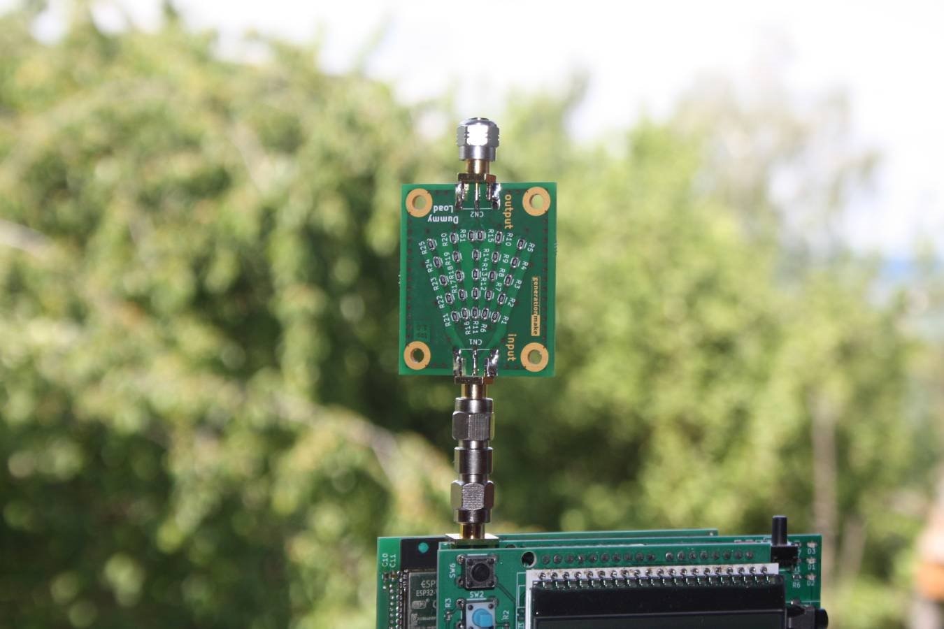
The real life hardware can be seen on the next picture. It looks very similar to the 3D model.
The hardware is released under CERN OHL v1.2 and all the data and documentation can be found on my project website ArduTrx - Dummy load There exists also a BOM with Farnell/Newark order numbers.
PCBs and parts for this project can also be ordered at Aisler: https://aisler.net/p/QEWPLPOW
If anyone rebuilds this project I wolud love to hear your experiences. If anyone has a network analyzer I would love to get a measurement and see how this dummy load performes in the GHz range. Just answer to this post or send me a message.
UPDATE july 24, 2019
I reworked the circuit according to the comments below the original blog post. The dummy load or attenuator is built now according to the following block diagram:
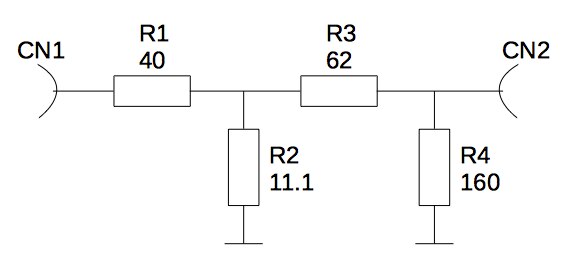
It now matches 50 ohm on the input and on the output. The downside of this is that the attenuator output is now -22.36 dB instead of -20 dB. The layout has only slightly changed.
There is now also a placement option possible where the device works only as a dummy load and has no attenuator output.
The updated data is on my website: ArduTrx - Attenuator or Dummy load
Nevertheless it still needs to be tested how the device behaves at higher frequencies.
Top Comments