


Introduction
This short blog post explores the difference between home-made, low-cost, a mid-cost and a high end 50 ohm load! They have many uses. The larger ones are often used to test transmitters, such as for Ham radio or Citizens' Band (CB) radio.

I used the Rohde & Schwarz FPC1500 Spectrum Analyzer in its Vector Network Analyzer (VNA) mode to examine them. There is more detail about the FPC1500 and how vector network analysis is used in the FPC1500 review here.

What are they used for and how do they work?
As mentioned a 50 ohm load has many uses! It is nearly always used with 50 ohm characteristic impedance cables. By using such a cable (often it is a coaxial cable but it could be a twisted pair cable, or two wires in parallel) then it is possible to send high frequency signals over long distances, for instance from board to board or between pieces of equipment. It is also possible to pass signals between an antenna and a radio receiver, or a transmitter and an antenna using such cables (they are known as transmission lines). For such a scheme to work, the cable needs to be connected to a load that has the same impedance as the cable’s characteristic impedance, which is usually 50 ohms (another popular value is 75 ohms).
During testing, it is common to remove the connected board or equipment or antenna, and replace it with a dummy device, to isolate and test an individual part of the entire system. For example, when testing radio transmitters it would not be good to connect the transmitter to a real antenna because it would be transmitting all sorts of junk during the test. Instead, a dummy device, known as a 50 ohm load or 50 ohm terminator, can be used. You can buy them or make them.
These 50 ohm loads or terminators look like a connector with one end sealed up. Inside, they contain a 50 ohm resistance with very little stray inductance or capacitance. If there is any additional inductance or capacitance, then the impedance doesn’t look like a real 50 ohms at all frequencies. A multimeter uses a small DC current to measure resistance and therefore the multimeter may well report that everything is fine with the 50 ohm load when in reality it could be performing badly at high frequencies.

Where to get them?
Cheap 50 ohm loads cost less than £1 from ebay. But, they are flawed at higher frequencies. A decent one should cost a lot more, and should come from a traceable source with a datasheet, unless you have a way to measure it (as mentioned, a multimeter is useless for this measurement).
Testing Them
With the FPC1500, I was able to measure 50 ohm loads, because it supports Vector Network Analyzer (VNA) capability. The way this works is to send signals at various frequencies through the cable to the 50 ohm load under test, and observe what signals are reflected back. If the load is a perfect 50 ohms, then all the power sent from the VNA is totally absorbed by the load, at all frequencies, and nothing gets reflected back. There are several ways to view the results; the return loss or Standing Wave Ratio (SWR) charts both indicate how much power was reflected back at different frequencies (frequency is on the x-axis). This is also known as a scalar measurement.
Another way to view the results is on a Smith chart. This is a two-dimensional representation where the horizontal line running through the center of the diagram is the line of real impedance. So, for a perfect 50 ohm load, we expect to see a point on that line (it happens that this point should be right in the center of the diagram). If there is any inductance or capacitance, then this is represented by a point above or below the line. It is drawn as a reactance, and the end result can be a curve or other shaped line as the VNA sweeps through the different frequencies. The perfect 50 ohm load should look like a single point for all frequencies, in the center of the diagram. For more detail, check the review mentioned earlier - it explains how to read the Smith chart.
Huber and Suhner 50 ohm SMA Terminator
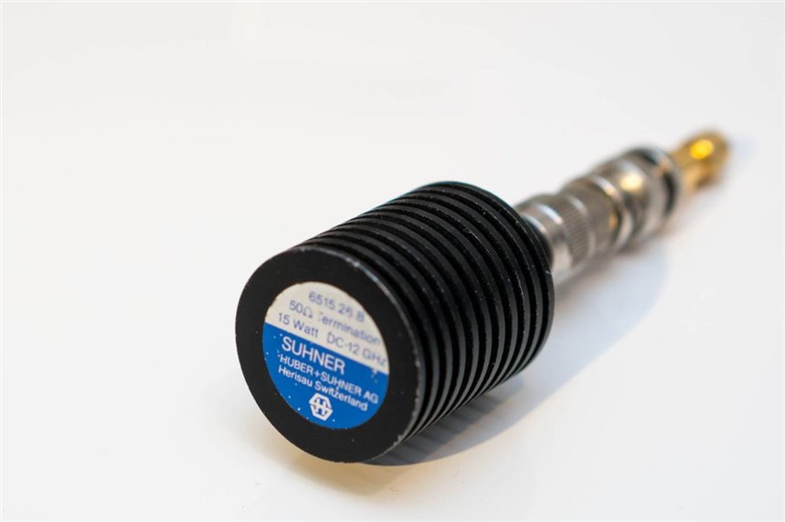
First off I examined the high quality load, which is a Huber and Suhner 50 ohm terminatorHuber and Suhner 50 ohm terminator. I tested between 2MHz and 3GHz. For this entire range, it looks like a single dot in the center of the display.
It is hard to see it, but it is right there in the center – at the position which represents 50 ohms (the position is marked 1 but the scale is 1:50).
The VSWR chart also shows what a good 50 ohm termination it really is – it is a nearly flat line of 1.0:1 VSWR for this entire frequency range. Toward the upper frequency range it reaches around 1.03:1 VSWR which is still tiny, and some of that will be due to cables and connectors.

Amphenol BNC Terminator
Next, I tried the Amphenol BNC terminatorAmphenol BNC terminator which costs a lot less. As can be seen, at higher frequencies it does not behave like a pure 50 ohm load. This is to be expected; it is a lower-cost terminator that is intended for coaxial cable based voice and data networks, and only needs to function well at up to a few hundred megahertz.
The VSWR chart also shows this to be the case; the marker is at 1GHz where it is already up to a VSWR value of 1.3:1 which is not great, and beyond 1.5GHz it really is extremely unusable. But as mentioned it was never intended for these frequencies.

Homemade 50 ohm Load
I also examined a homemade 50 ohm load. My excuse is that I built this as a teenager : ) In any case, high frequency for me at that time was 27MHz, and that was what I created this load for, for playing around with citizens’ band (CB) radio.

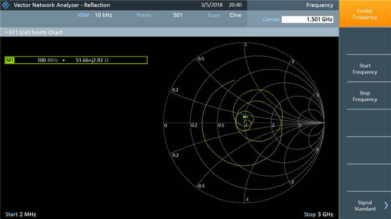
You can see internally it just consists of twenty 1k ohm resistors, all in parallel, to provide 50 ohms. The center junction forms one end of the parallel resistors and it is connected to the coax center wire. The outer ends form the other side of the parallel resistors, and are connected to the coax shield and the enclosure with the screws and solder tags.

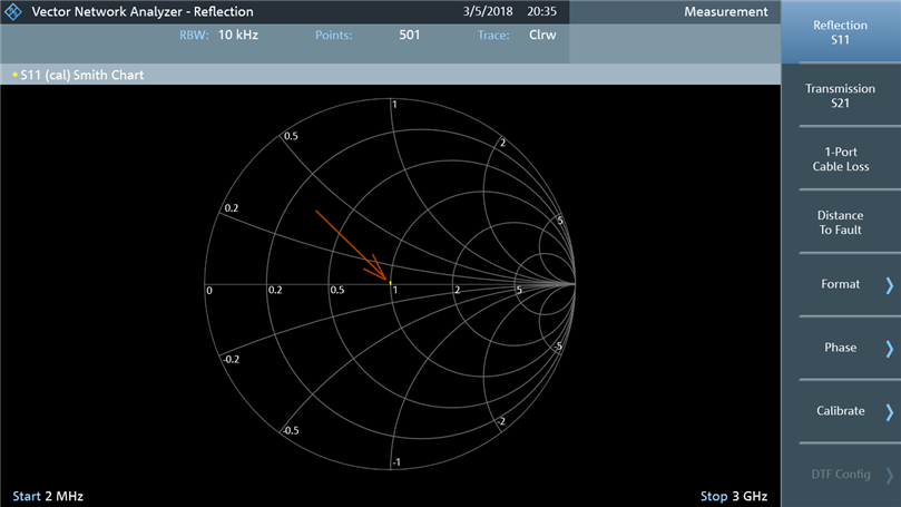
The marker is set at 100MHz; beyond a few tens of MHz, it is completely useless as a 50 ohm load : ) In fact at some frequencies (near the left side of the Smith chart) it looks like a near short circuit, and at others (near the right side of the chart) it looks like a very high resistance : )

Huber and Suhner 15W Load
And finally I took a look at an off-the-shelf load which would have cost around $200 when new. Again, ebay should be avoided for cheap ones.. they may have some branding on them but that could be fake, and you wouldn't know for sure without testing it, and could damage the attached equipment if there is a mismatch, i.e. causing power to be not absorbed. This particular Huber and Suhner 15W load is pretty old but genuine.
Unfortunately I have a chain of RF adapters attached to it, and some are very old. If I replaced them, I’d get better results. But I would not have known that for sure without applying it to the VNA. I had to unscrew and tighten several times to get it ‘just right’. I will purchase new adapters now, as a result of seeing the results on the VNA. The Smith chart shows the slight mismatch across the frequency range.

The VSWR was under 1.2:1, across the entire 3GHz span which is quite good, but I know this load is capable of better results without that old chain of connectors.

Summary
When it comes to 50 ohm loads and terminations, I think it is definitely worth investing in decent ones especially if you’re planning on using it at frequencies higher than a few hundred megahertz. The small Huber and Suhner 50 ohm terminatorHuber and Suhner 50 ohm terminator is under $20, which is really good value, confirmed from the results from the FPC1500 in VNA mode.

Top Comments