| Enter Your Project for a chance to win a grand prize for the most innovative use of Arduino or a $200 shopping cart! The Birthday Special: Arduino Projects for Arduino Day! | Project14 Home |
| Monthly Themes | ||
| Monthly Theme Poll |

The goal:
The goal of this project is to make an ESC (electronic speed controller) using an arduino as brain and a self made board as output stage, I also decided to not use any commercial available motor driver because I wanted to learn how a brushless motor works and how I can control it (without using sensors).
The learning process:
Internet is full of video/application notes about this topic, but for the very basic understanding on how a ESC works I found these two video very helpful:
https://www.youtube.com/watch?v=W9IHEqlGG1s
https://www.youtube.com/watch?v=8LXPcJD6hEA
This application notes was very helpful too: http://ww1.microchip.com/downloads/en/AppNotes/00857B.pdf
At the end, I made a bit of reverse engineering with an old ESC.
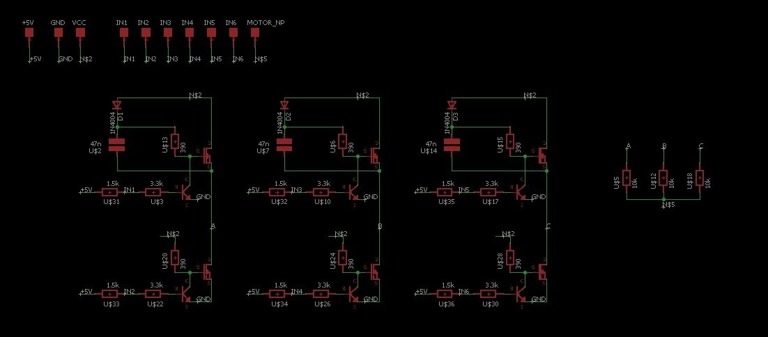
Let's build the output stage:
Arduino has a current limit of about 20mA for each pin, so it can not power up a motor directly, hence I designed a small board to drive the motor. The board is very simple, and to make all even easier I decided to start with a small motor from a CD player and only 3.3V as power supply (so I didn't need to bootstrap the signal for the upper portion of the board and arduino can read it). The result was this:
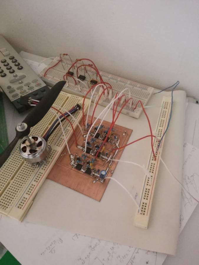
Since a while ago I made a cnc engraver (with you guessed it, an arduino), I decided to make the board with this machine to test it, after a couple attempts I managed to get my board....
....and then I soldered all the components.
Time to code
This part was the most time consuming so I will not explain all the iterations that I made to the code (I made 34 different versions of it), instead I will focus on the basic principle, which (in teory) is very simple: you have to power up motor's coils in a certain order so the rotor will follow the rotating magnetic field created by the windings, the problem is that without sensors you don't know the rotor angular position, so you have to estimate it using the bemf (back electromotive force) generated by a floating phase (if you don't know what I mean watch the video linked at the beginning of this post  ).
).
After a lot of troubleshooting I finally managed to obtain my first functioning code:
From this I continued to improve the code by setting up faster ADC readings (and optimizing when to do this readings), adding acceleration control and a crude brake and also by implementing the control using a standard RC remote controller, the code that I obtained is this:


/*board pinout:
 *   bjt1   bjt3   bjt5
 *    4      6      8       R-R-R
 *
 *   bjt2   bjt4   bjt6
 *    5      7      9
 * (leg 1) (leg 2) (leg 3)
 * phase sequence: b1b4 b1b6 b3b6 b3b2 b5b2 b5b4 ok
 * bemf reading: a1 a2 a3
 * motor virtual neutral  point: a4
 * interrupt pin 2, 3 for remote controller
 */

const byte mask=B01000000;//mask for start of conversion & state of conversion
const byte deadvalue=30;//if under this value deactivate all
const unsigned int minimum=950;//min on period for receiver signal (us)
const unsigned int maximum=2130;//max on period for receiver signal (us)
const unsigned int timelimit=10000;
const byte switchpoint=100;//39%
const byte addhigh=1;//increment after switch point
const byte addlow=15;//increment before switch point

unsigned long t;//time variable
unsigned int d1;//tempo impulso
byte dmax;
byte soglia;
byte fase=0;//phase state
volatile boolean input=0;//if 1->received a new pulse from the receiver
boolean brake=0;//brake flag
boolean high=0;//phase active flag
byte neutral=80;//neutral point value
byte emread=0;//floating phase reading
boolean delta=0;//1=negative, 0=positive, if the two deltas are different I've crossed the neutral point
boolean lastdelta=1;
byte datacomp=0;

void setup() {
  DDRD= (0<<ddd2)|(0<<ddd3)|(1<<ddd4)|(1<<ddd5)|(1<<ddd6)|(1<<ddd7); define="" pin="" 4...7="" as="" output,="" 2="" 3="" input="" interrupt<br="">  DDRB= (1<<ddb0)|(1<<ddb1); pin="" 8,9="" as="" output<br="">  EICRA|=(1<<isc01)|(1<<isc00); int0="" (pin2)="" rising<br="">  EICRA|=(1<<isc11); int1="" (pin3)="" falling<br="">
  ADMUX=B01100000;//I'm using input A0,result is left adjusted
  DIDR0=0b00111111;//shut off digital input for A0...A5
  ADCSRA=B11000011;//I'm using 8 as division factor,with 4 I obtain quite noisy measurements
  //adc in free running
  setA0();
  startofconversion();//calibration conversion


  for(unsigned int i=0;i<300;i++){//let's make some sound with phase 6
    PORTD=(1<<pd7);
    PORTB=(1<<pb0);
    delayMicroseconds(150);
    PORTD=(0<<pd7);
    PORTB=(0<<pb0);
    delayMicroseconds(350);
  }
  delay(100);
  for(unsigned int i=0;i<300;i++){
    PORTD=(1<<pd7);
    PORTB=(1<<pb0);
    delayMicroseconds(150);
    PORTD=(0<<pd7);
    PORTB=(0<<pb0);
    delayMicroseconds(350);
  }
  delay(300);
  for(unsigned int i=0;i<400;i++){
    PORTD=(1<<pd7);
    PORTB=(1<<pb0);
    delayMicroseconds(100);
    PORTD=(0<<pd7);
    PORTB=(0<<pb0);
    delayMicroseconds(330);
  }
  PORTD=(0<<pd4)|(0<<pd5)|(0<<pd6)|(0<<pd7); all="" output="" to="" zero<br="">  PORTB=(0<<pb0)|(0<<pb1); <br="">
  //timer2 setup
  TCCR2A=(1<<wgm21)|(1<<wgm20); fast="" pwm<br="">  TCCR2B=(1<<cs21); divider="" a="" 8<br="">  TIMSK2=(1<<ocie2b)|(1<<toie2); enable="" flags="" for="" interrupt<br="">  OCR2B=0;//0%DC

  EIMSK|=(1<<int1)|(1<<int0); interrupt="" enable="" int0="" int1<br="">  //Serial.begin(250000);//debug
}

void loop() {
  if(input==1 & d1<1600){//assign DC (duty cicle)
    dmax=(1600-d1)/2.6;
    brake=0;
  }
  else{
    if(d1>1700){
      dmax=(d1-1700)/2;
      brake=1;
    }
  }
  //acceleration control
  soglia=OCR2B;
  if(sogliatimelimit){//da 0 a 255 in 2 secondi ca con timelimit 10000
    t=micros();
    if(soglia<switchpoint){
      OCR2B+=addlow;
    }
    else{
      OCR2B+=addhigh;
    }
  }
  else{
    if(dmax<soglia)
      OCR2B=dmax;//deceleration
  }
  if(input==1 & high){//check motor neutral point only every 20 ms (receiver frequency at 50Hz)
    setA4();
    startofconversion();
    neutral=waitandget();
    //Serial.println(neutral);//debug
    input=0;
  }

  if(high){//lset reading for bemf on the floating phase
    switch(fase){
      case 1:
        setA3();
        startofconversion();
        break;

      case 2:
        setA2();
        startofconversion();
        break;

      case 3:
        setA1();
        startofconversion();
        break;

      case 4:
        setA3();
        startofconversion();
        break;

      case 5:
        setA2();
        startofconversion();
        break;

      case 6:
        setA1();
        startofconversion();
        break;
    }//fine switch
    emread=waitandget();//get the data
    if(emread-neutral>0){
      delta=0;
    }
    else{
      delta=1;
    }
    //Serial.println(fase);//debug
  }//fine if high

  //cli();//disable all interrupts
  if(lastdelta==0 & delta==1){//check "zero cross"
      lastdelta=1;
      fase++;
    }

    if(lastdelta==1 & delta==0){//check "zero cross"
      lastdelta=0;
      fase++;
    }

    if(fase>6)
      fase=1;
    //sei();//enable all interrupts
}

//------------------------------ADC's functtions--------------
void startofconversion()
{
  ADCSRA=ADCSRA|mask;//let's start a conversion!
}

byte waitandget()
{
  while((ADCSRA&mask)==mask)//wait
  {
  }

  return ADCH;
}

void setA0(){
  ADMUX=0b01100000;
}

void setA1(){
  ADMUX=B01100001;
}

void setA2(){
  ADMUX=0b01100010;
}

void setA3(){
  ADMUX=0b01100011;
}

void setA4(){
  ADMUX=0b01100100;
}

//---------------------------ISR (interrupt service routine) for input signal-------------------------
ISR(INT0_vect){//void up(){
  t=micros();
}

ISR(INT1_vect){//void down(){
  t=micros()-t;
  d1=t;
  if(d1>minimum & d1<maximum){
    input=1;//set the flag, input signal received
  }
}

//-----------------------------ISR timer2 pwm-----------------------------
ISR(TIMER2_COMPB_vect){
  PORTD=(0<<pd4)|(0<<pd5)|(0<<pd6)|(0<<pd7); all="" output="" to="" zero<br="">  PORTB=(0<<pb0)|(0<<pb1); <br="">  high=0;//flag: all phases are shut off
 // Serial.println(OCR2B);
}

ISR(TIMER2_OVF_vect){//
  if(brake){//
    PORTD=(1<<pd5);
  }
  else{//accelerator routine
    if(OCR2B>deadvalue){
    switch(fase){
      case 1:
        PORTD=(1<<pd4)|(1<<pd7);
        break;

      case 2:
        PORTD=(1<<pd4);
        PORTB=(1<<pb1);
        break;

      case 3:
        PORTD=(1<<pd6);
        PORTB=(1<<pb1);
        break;

      case 4:
        PORTD=(1<<pd6)|(1<<pd5);
        break;

      case 5:
        PORTB=(1<<pb0);
        PORTD=(1<<pd5);
        break;

      case 6:
        PORTB=(1<<pb0);
        PORTD=(1<<pd7);
        break;
    }
    high=1;//flag: phases are active
  }//fine if deadvalue
  }
}
Further improvements:
Now that I have a working prototipe I can improve it, first of all I'm working on a beefier board that can handle more that 3.3V (and also more current than the previous board), I'm also working on the "position tracking" of the rotor, because one adc reading take up "a lot" of time, so the next iteration is to make a circuit that give to arduino a digital signal to read (much faster and reliable compared to an "analog read"), basically it is an array of three comparator with a level shift.
On the software side I want to add a better brake/acceleration control, the "fail safe" feature, the possibility to modify/ store the settings in the EEPROM and so on... basically I want to obtain a fully functioning ESC to test on myRC car  .
.
At the moment I haven't the time to complete the project as I should do (it's quite a time consuming project and I have to study), but the version 2 of the output stage is almost ready
Have a nice day!