element14 Community
element14 Community
    Register Log In
  • Site
  • Search
  • Log In Register
  • About Us
  • Community Hub
    Community Hub
    • What's New on element14
    • Feedback and Support
    • Benefits of Membership
    • Personal Blogs
    • Members Area
    • Achievement Levels
  • Learn
    Learn
    • Ask an Expert
    • eBooks
    • element14 presents
    • Learning Center
    • Tech Spotlight
    • STEM Academy
    • Webinars, Training and Events
    • Learning Groups
  • Technologies
    Technologies
    • 3D Printing
    • FPGA
    • Industrial Automation
    • Internet of Things
    • Power & Energy
    • Sensors
    • Technology Groups
  • Challenges & Projects
    Challenges & Projects
    • Design Challenges
    • element14 presents Projects
    • Project14
    • Arduino Projects
    • Raspberry Pi Projects
    • Project Groups
  • Products
    Products
    • Arduino
    • Avnet Boards Community
    • Dev Tools
    • Manufacturers
    • Multicomp Pro
    • Product Groups
    • Raspberry Pi
    • RoadTests & Reviews
  • Store
    Store
    • Visit Your Store
    • Choose another store...
      • Europe
      •  Austria (German)
      •  Belgium (Dutch, French)
      •  Bulgaria (Bulgarian)
      •  Czech Republic (Czech)
      •  Denmark (Danish)
      •  Estonia (Estonian)
      •  Finland (Finnish)
      •  France (French)
      •  Germany (German)
      •  Hungary (Hungarian)
      •  Ireland
      •  Israel
      •  Italy (Italian)
      •  Latvia (Latvian)
      •  
      •  Lithuania (Lithuanian)
      •  Netherlands (Dutch)
      •  Norway (Norwegian)
      •  Poland (Polish)
      •  Portugal (Portuguese)
      •  Romania (Romanian)
      •  Russia (Russian)
      •  Slovakia (Slovak)
      •  Slovenia (Slovenian)
      •  Spain (Spanish)
      •  Sweden (Swedish)
      •  Switzerland(German, French)
      •  Turkey (Turkish)
      •  United Kingdom
      • Asia Pacific
      •  Australia
      •  China
      •  Hong Kong
      •  India
      •  Korea (Korean)
      •  Malaysia
      •  New Zealand
      •  Philippines
      •  Singapore
      •  Taiwan
      •  Thailand (Thai)
      • Americas
      •  Brazil (Portuguese)
      •  Canada
      •  Mexico (Spanish)
      •  United States
      Can't find the country/region you're looking for? Visit our export site or find a local distributor.
  • Translate
  • Profile
  • Settings
Personal Blogs
  • Community Hub
  • More
Personal Blogs
Legacy Personal Blogs Arduino rejuvenates an elderly Real Robots/Eaglemoss publications Cybot - Part 1
  • Blog
  • Documents
  • Mentions
  • Sub-Groups
  • Tags
  • More
  • Cancel
  • New
  • Share
  • More
  • Cancel
Group Actions
  • Group RSS
  • More
  • Cancel
Engagement
  • Author Author: neilk
  • Date Created: 11 Mar 2015 5:06 PM Date Created
  • Views 3296 views
  • Likes 5 likes
  • Comments 6 comments
  • xh250
  • real_robots
  • eaglemoss
  • cybot
  • h-bridge
  • arduino
  • l9110
Related
Recommended

Arduino rejuvenates an elderly Real Robots/Eaglemoss publications Cybot - Part 1

neilk
neilk
11 Mar 2015

More years ago than I care to remember (probably 15), I foolishly subscribed to a magazine called Real Robots, published by Eaglemoss. Each monthly part included components which, when you had spent a small fortune buying the magazine, would let you build a robot - Cybot.


I became disillusioned when I realised that all I would be doing was screwing mechanical parts together and plugging in already fully populated PCBs, some of which carried pre-programmed microprocessors: I had assumed more involvement.


By the time I cancelled my subscription I had a 3 wheeled base driven by 2 independent DC motors, with a line follower module,


imageimage

and a collection of sensors and circuit boards. These were all packed away when I moved house 10 years ago and only unpacked recently when I did some work with lego and a stepper motor and remembered poor old Cybot.


imageimage

There a few websites devoted to Cybot and one in particular: http://lpilsley.co.uk/cybot/index.htm,  is very useful. The site includes functional descriptions of the circuit boards and some reverse engineered circuit diagrams.


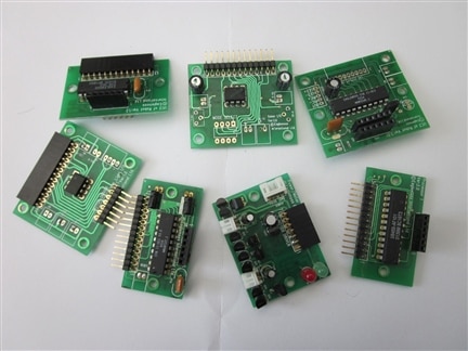
Bearing in mind the relative antiquity of anything designed and built around 15 years ago, I decided to keep the sensors (for now) and scrap all the circuit boards, pausing only to carefully unsolder the small, white 2, 3 and 4 pin connectors, which mate with plugs on the sensor leads.


These connectors have proved difficult to identify - I did eventually track them down as XH250 series which are, annoyingly, 2.50 mm pitch! The 2 pin connectors will fit 2.54 mm pitch holes, anything more than 2 pins varies from a struggle to totally impossible. I wouldn't choose to use them. If anyone is interested, the connectors can be found here: http://www.toby.co.uk/content/catalogue/products.aspx?series=XH250-xx-H  and a similar connector is available 2.54 mm pitch


My first requirement for the rejuvenation process was a motor drive board:


I tested the motors on  6 V and they draw about 250 mA, well within the capabilities of the L9110  H-Bridge chip - 800 mA continuous.


I sourced this board, which carries two L9110 chips, from eBay, for a very modest sum. It can drive 2 DC motors or 1 stepper motor.

image


The motors leads were terminated with the 2 pin connectors mentioned earlier. Rather than clip them off, I made up some extension leads, using the salvaged connectors from the scrapped circuit boards:


imageimage


The other ends of the extensions then connect directly into the screw terminal outputs of the L9110 board.


Driving the L9110 and the motors

There is plenty of guidance on how to write a sketch to test the L9110 board and the motors, in particular:


https://www.bananarobotics.com/shop/How-to-use-the-HG7881-%28L9110%29-Dual-Channel-Motor-Driver-Module


and:


http://www.bajdi.com/l9110-h-bridge-module/


The bananarobotics link includes a truth table for the L9110 and an Arduino sketch to control a single motor. I tried the sketch and was pleased to see that it worked precisely as expected. However, the way in which the variables were defined was a little cumbersome for my own coding style, so I modified all of that and then created a set of functions to replace the original in-line code.


Everything still worked fine, but there was still a bit of potential confusion because,  although the sketch uses 2 PWM capable digital pins - 10 and 11, only pin 10 is actually used in PWM mode,  whilst 11  - the "direction" pin - is either high or low. This results in a need to fiddle with the PWM duty cycle between forward and reverse to get the same speed. The following code segment (using my version) should make this clear:


#define B_IA 10                 // D10 --> Motor B Input A
#define B_IB 11                 // D11 --> Motor B Input B

#define motorBSpeed B_IA        // Motor B PWM Speed
#define motorBDirection B_IB    // Motor B Direction


void forward(int thisSpeed)
{
  softStop();
  delay( DIR_DELAY );
// set the motor speed and direction
  digitalWrite( motorBDirection, HIGH ); // direction = forward
  analogWrite( motorBSpeed, 255-thisSpeed );
}

void reverse(int thisSpeed)
{
  softStop();
  delay( DIR_DELAY );
// set the motor speed and direction
  digitalWrite( motorBDirection, LOW ); // direction = reverse
  analogWrite( motorBSpeed, thisSpeed );
}

As can be seen:

  1. in forward mode, the PWM duty cycle is set to be ( 255 - desired speed ), with direction pin high
  2. in reverse mode, the PWM duty cycle is set to be ( desired speed ), with the direction pin low


In order to achieve the same speed in both directions. This seemed a little confusing.


I then got into a bit of trouble when I modified the sketch to control 2 motors - I assigned pins 8 and 9 for the second motor, keeping things in order. I didn't remember that pin 8 is NOT PWM, so it didn't work properly. I had to switch 8 and 9 around. I got there in the end!


I then took a detailed look at the sketch provided by Bajdi. This uses all the pins in PWM mode and presents a very straightforward view of the speed issue. I preferred the Bananarobotics menu driven approach so I changed the pin assignments and the detail of the functions in my own sketch to use those from Bajdi's example:


const int AIA = 9;  // (pwm) pin 9 connected to pin A-IA
const int AIB = 5;  // (pwm) pin 5 connected to pin A-IB
const int BIA = 10; // (pwm) pin 10 connected to pin B-IA
const int BIB = 6;  // (pwm) pin 6 connected to pin B-IB


void forward(byte thisSpeed)
{
  softStop();
  delay(pause);
  // set the motor speed and direction
  analogWrite(AIA, thisSpeed);
  analogWrite(AIB, 0);
  analogWrite(BIA, thisSpeed);
  analogWrite(BIB, 0);
}

void reverse(byte thisSpeed)
{
  softStop();
  delay(pause);
  // set the motor speed and direction
  analogWrite(AIA, 0);
  analogWrite(AIB, thisSpeed);
  analogWrite(BIA, 0);
  analogWrite(BIB, thisSpeed);
}


I hope most people will agree that this is far less confusing.


I then added Left and Right turn functions into my sketch. In the example given by Bajdi, the two motors were run in opposite directions. This produces a "spin" rather than a turn. I decided to change it so that both motors run in the same direction, but one runs slower than the other.


At this point, the Cybot is upside down, so that I can run the motors; the motor drive board is powered from a breadboard 5 V PSU and the Arduino UNO is still connected to my PC so that it gets power and I can control the motors via the serial monitor.


In my next Blog post I will add Bluetooth communication to the Cybot and also liberate the Aruino and the motor driver board by running them from batteries (separate, of course).


The Arduino Sketch up to this point is attached.


Attachments:
_2_Motor_basic_after_Bajdi_with_turns.zip
  • Sign in to reply

Top Comments

  • gadget.iom
    gadget.iom over 10 years ago +1
    Looking good. Interested to see how it develops.
  • neilk
    neilk over 10 years ago in reply to gadget.iom +1
    gadget.iom Thanks Paul
  • neilk
    neilk over 10 years ago in reply to Former Member +1
    Hi tasi I would love to help you but although I still have the line-follower module ,I haven't tried to use it with an Arduino yet. However, if you look here: http://lpilsley.co.uk/cybot/follower.htm You…
Parents
  • gadget.iom
    gadget.iom over 10 years ago

    Looking good. Interested to see how it develops.

    • Cancel
    • Vote Up +1 Vote Down
    • Sign in to reply
    • More
    • Cancel
  • Former Member
    Former Member over 10 years ago in reply to gadget.iom

    Hi there,


    Sorry my english, but i will try explain.


    I'm doing a similar project , and still could not get to work the line follower sensor. Got any tips ?

    I try to test first one pair and work, when i do the something in other pair don't work.


    The test i made, first plug in the yellow line to 5V of arduino, the black line to ground and the blue line to analog pin A0, and made the sketch that just show if detect the line. This work fine, but when i tried make the same but just with orange line, that show always detect the line. And when i plug in the 2 lines (blue and orange) don't work anything.


    When i make the test just with the orange line, i see on arduino the TX and RX led always on.


    Thank you for your help

    TS

    • Cancel
    • Vote Up 0 Vote Down
    • Sign in to reply
    • More
    • Cancel
  • neilk
    neilk over 10 years ago in reply to Former Member

    Hi tasi I would love to help you but although I still have the line-follower module ,I haven't tried to use it with an Arduino yet.


    However, if you look here:  http://lpilsley.co.uk/cybot/follower.htm


    You will find a schematic of the Cybot line follower module - IR LEDs and Photo Diodes - and an explanation of how they should work.


    Hope this helps - when I get round to using it with my Arduino, I will certainly post my results. Please post yours if you get it working.


    Good Luck


    Neil

    • Cancel
    • Vote Up +1 Vote Down
    • Sign in to reply
    • More
    • Cancel
Comment
  • neilk
    neilk over 10 years ago in reply to Former Member

    Hi tasi I would love to help you but although I still have the line-follower module ,I haven't tried to use it with an Arduino yet.


    However, if you look here:  http://lpilsley.co.uk/cybot/follower.htm


    You will find a schematic of the Cybot line follower module - IR LEDs and Photo Diodes - and an explanation of how they should work.


    Hope this helps - when I get round to using it with my Arduino, I will certainly post my results. Please post yours if you get it working.


    Good Luck


    Neil

    • Cancel
    • Vote Up +1 Vote Down
    • Sign in to reply
    • More
    • Cancel
Children
  • Former Member
    Former Member over 10 years ago in reply to neilk

    Hello,


    Thanks for your help, i will try again and again, and when i have te result i post here.


    TS

    • Cancel
    • Vote Up +1 Vote Down
    • Sign in to reply
    • More
    • Cancel
element14 Community

element14 is the first online community specifically for engineers. Connect with your peers and get expert answers to your questions.

  • Members
  • Learn
  • Technologies
  • Challenges & Projects
  • Products
  • Store
  • About Us
  • Feedback & Support
  • FAQs
  • Terms of Use
  • Privacy Policy
  • Legal and Copyright Notices
  • Sitemap
  • Cookies

An Avnet Company © 2025 Premier Farnell Limited. All Rights Reserved.

Premier Farnell Ltd, registered in England and Wales (no 00876412), registered office: Farnell House, Forge Lane, Leeds LS12 2NE.

ICP 备案号 10220084.

Follow element14

  • X
  • Facebook
  • linkedin
  • YouTube