element14 Community
element14 Community
    Register Log In
  • Site
  • Search
  • Log In Register
  • Community Hub
    Community Hub
    • What's New on element14
    • Feedback and Support
    • Benefits of Membership
    • Personal Blogs
    • Members Area
    • Achievement Levels
  • Learn
    Learn
    • Ask an Expert
    • eBooks
    • element14 presents
    • Learning Center
    • Tech Spotlight
    • STEM Academy
    • Webinars, Training and Events
    • Learning Groups
  • Technologies
    Technologies
    • 3D Printing
    • FPGA
    • Industrial Automation
    • Internet of Things
    • Power & Energy
    • Sensors
    • Technology Groups
  • Challenges & Projects
    Challenges & Projects
    • Design Challenges
    • element14 presents Projects
    • Project14
    • Arduino Projects
    • Raspberry Pi Projects
    • Project Groups
  • Products
    Products
    • Arduino
    • Avnet & Tria Boards Community
    • Dev Tools
    • Manufacturers
    • Multicomp Pro
    • Product Groups
    • Raspberry Pi
    • RoadTests & Reviews
  • About Us
  • Store
    Store
    • Visit Your Store
    • Choose another store...
      • Europe
      •  Austria (German)
      •  Belgium (Dutch, French)
      •  Bulgaria (Bulgarian)
      •  Czech Republic (Czech)
      •  Denmark (Danish)
      •  Estonia (Estonian)
      •  Finland (Finnish)
      •  France (French)
      •  Germany (German)
      •  Hungary (Hungarian)
      •  Ireland
      •  Israel
      •  Italy (Italian)
      •  Latvia (Latvian)
      •  
      •  Lithuania (Lithuanian)
      •  Netherlands (Dutch)
      •  Norway (Norwegian)
      •  Poland (Polish)
      •  Portugal (Portuguese)
      •  Romania (Romanian)
      •  Russia (Russian)
      •  Slovakia (Slovak)
      •  Slovenia (Slovenian)
      •  Spain (Spanish)
      •  Sweden (Swedish)
      •  Switzerland(German, French)
      •  Turkey (Turkish)
      •  United Kingdom
      • Asia Pacific
      •  Australia
      •  China
      •  Hong Kong
      •  India
      • Japan
      •  Korea (Korean)
      •  Malaysia
      •  New Zealand
      •  Philippines
      •  Singapore
      •  Taiwan
      •  Thailand (Thai)
      • Vietnam
      • Americas
      •  Brazil (Portuguese)
      •  Canada
      •  Mexico (Spanish)
      •  United States
      Can't find the country/region you're looking for? Visit our export site or find a local distributor.
  • Translate
  • Profile
  • Settings
Personal Blogs
  • Community Hub
  • More
Personal Blogs
Legacy Personal Blogs Charactersitics of a Small Buck-Boost Convertor
  • Blog
  • Documents
  • Mentions
  • Sub-Groups
  • Tags
  • More
  • Cancel
  • New
  • Share
  • More
  • Cancel
Group Actions
  • Group RSS
  • More
  • Cancel
Engagement
  • Author Author: dubbie
  • Date Created: 22 May 2020 12:13 PM Date Created
  • Views 2110 views
  • Likes 9 likes
  • Comments 7 comments
  • buck-boost
  • dc-dc
  • efficiency
Related
Recommended

Charactersitics of a Small Buck-Boost Convertor

dubbie
dubbie
22 May 2020

For my mobile robots I have traditionally used AA or AA batteries as power sources, which is fine but does mean that there is a minimum size of chassis that is needed and that the motors need to be more powerful in order to move the heavy batteries about. For some time I have been toying with the idea of moving to LiPo batteries and/or using solar cells to power the mobile robots (Solar Cell On A Sunny Day ) and it seems to me that these power sources need a DC-DC convertor ,as they provide a lower voltage or a more varying voltage. I still like to work at 5V for the Nanos and 6V for the motors so decided I needed a buck-boost convertor. I am barely knowledgeable about what buck-boost convertors do or how they work, or even if they are very good, but I decided I wanted the input voltage to be useable both below and above the output voltage, plus I wanted to be able to vary the output voltage as I am still experimenting and not sure what output voltage is optimum for me. Plus it needs to be low cost as I might want several of them for a herd of walking robots I have in mind. I discovered this system on the internet:


image


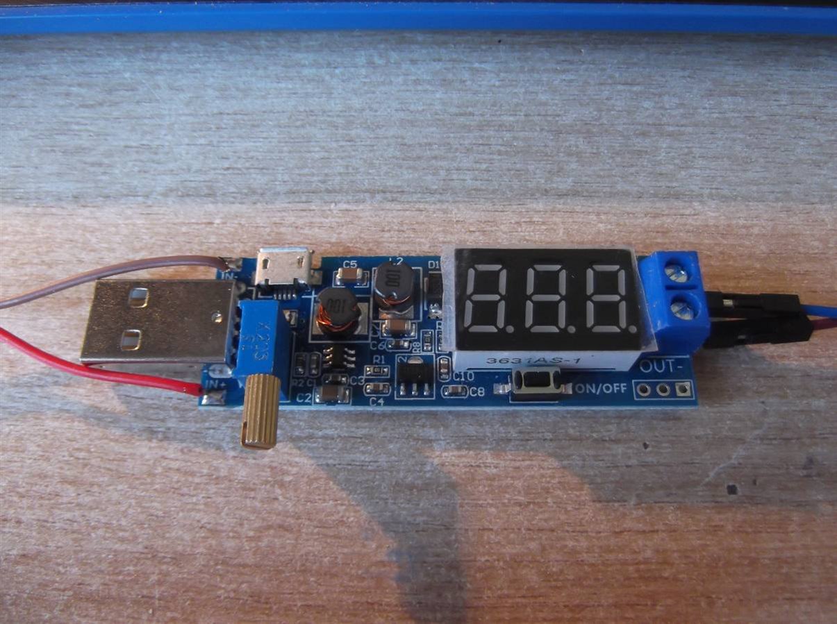
It's really designed to be used with a USB input, either the standard or a micro connector but solder pads are provided for a wired input which is what I will be using mostly. I'm sure there's a microcontroller on there somewhere but I cannot see it. There is a 3 digit seven segment LED display for showing the output voltage and screw terminals for the output connections. As with many of these boards there is no schematic or information so I have no idea whether the input ground is separated from the output ground, but as it is low voltage I'm assuming not. There is a sufficiently large brass knob on the multi-turn potentiometer (blue) on the left that allows precise control of the output voltage. There is a small button below the seven segment display that controls the output and the display. Short presses on this button turn the output ON and OFF, a long press and hold can be used to turn the display ON or OFF in whatever state the output is in. It's quite a clever single button controlled user interface. The only downside of this module is that I could not find a local seller and had  to wait 4 weeks or more for it to arrive from China. There are alternatives that have switched outputs but I wanted this infinitely variable version.


As there was no information that I could find on this module I decided to measure it's characteristics myself. So I used a bench power supply as the input and to measure the input voltage, a multimeter to measure the input current, another multimeter to measure the output current and the seven segment display to measure the output voltage. I only have two multimeters and the seven segment display seemed to be quite accurate which is why I used it. For the load I used a low cost resistor box. I have looked inside this resistor box and it uses surface mount resistors which is fine for the higher resistances but for the smaller values say under 50 Ohms I am a bit dubious about their ability to dissipate the heat without melting the solder and falling off so I have limited my measurements. Plus the multimeters only have current ranges up to 200 mA so any values larger than that I cannot measure anyway. I'm not really interested in trivial output currents so selected a maximum resistance load of 900 Ohms, down to 30 or 40 Ohms.


You don't have permission to edit metadata of this video.
Edit media
x
image
Upload Preview
image


There are two parameters I am interesting in, the stability of the output voltage and the efficiency of the module. I have not shown the output voltage here but it never changed from the set value during all the measurements so either it is very good or I just happened to select the output voltage (5.0V)  that works really well. The efficiency is calculated in Google Sheets using power out divided by power in. For all these measurements I maintained the seven segment display to be on which obviously consumes some current. I did not have any direct method of measuring the LED currents but measured the input current with the LEDs ON, measured it again with them OFF, calculated the number of segments on and divided that into the current difference. For an output of 5.0V there are seventeen segments on.


Segment current = (Input current LEDS on - Input current LEDs off) / Number of segments on


and this provides a individual segment current of 0.6 mA.


Efficiency = (Vout * Iout)/(Vin * Iin) * 100%


For low output currents the efficiency will appear much lower as the seven segment display is consuming power.


I took two series of measurements, one with an input voltage of 5.0V and the second with an input voltage of 3.7V, both with an output voltage of 5.0V.


image


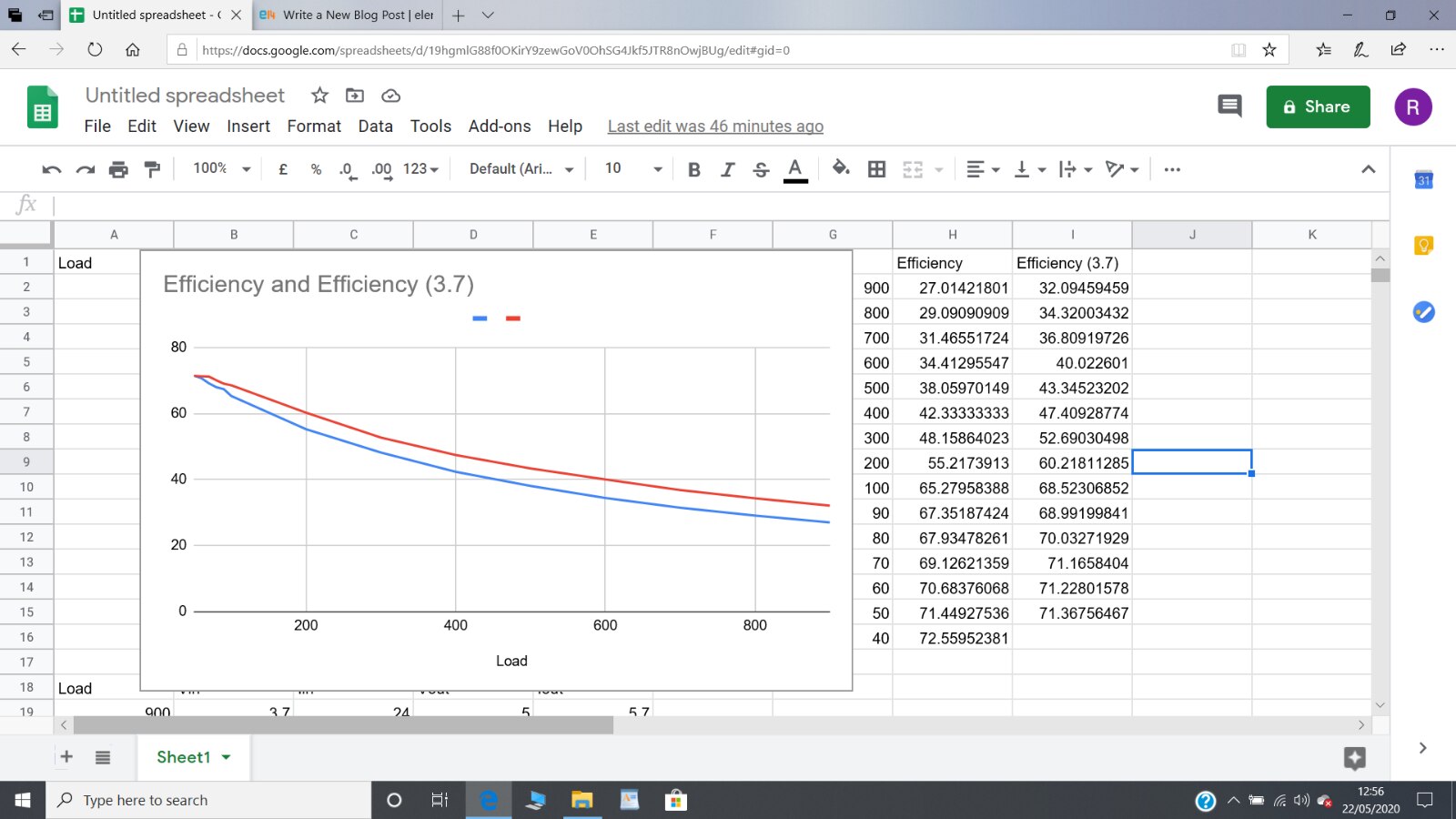
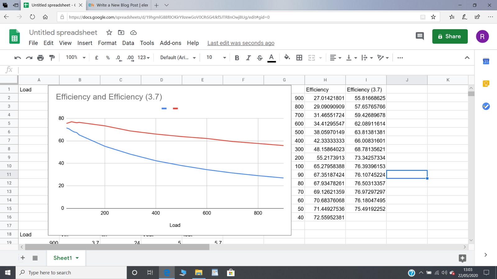
I am aware from the little knowledge that I have that this type of DC-DC convertor has a better efficiency the harder it is worked, which is illustrated by these graphs. The maximum efficiency of 71-72% is achieved at the highest output current (120 mA) that I could measure (40 Ohms). The efficiency is much lower at the lower output currents (900 Ohms load  giving 5.7 mA output current).


For comparison I have subtracteded the seven segment display current from the input current just for the input voltage of 3.7V (the red trace) and the efficiency at lower output currents is much improved, as would be expected.


image


I had been hoping for a higher efficiency than was achieved but this module does it's job and it looks like it will be useful for me on my mobile robots. The next step will be to try it out with a real LiPo battery and real solar cells.


Dubbie

  • Sign in to reply

Top Comments

  • shabaz
    shabaz over 5 years ago +5
    Hi Dubbie, Just to throw another idea out there, it could be an option to operate from two cells, i.e. operating from circa 7-8.4V rather than a single LiPo, and then have a single buck converter (or even…
  • genebren
    genebren over 5 years ago +5
    I have done some experimenting with boost converters, using Li-Ion batteries (and some LiPo). It is possible to achieve higher efficiencies, but a lot of this has to do with component selections. Here…
  • jw0752
    jw0752 over 5 years ago +4
    Hi Dubbie, I have had a lot of fun working with these little DC to DC converter modules. I enjoyed your blog on the experiment and I hope you post how the module works out for your robots. John
Parents
  • shabaz
    shabaz over 5 years ago

    Hi Dubbie,


    Just to throw another idea out there, it could be an option to operate from two cells, i.e. operating from circa 7-8.4V rather than a single LiPo, and then have a single buck converter (or even just a linear regulator if the microcontroller doesn't need much power) for 5V. The motors could operate from the battery voltage in that case, if they can operate over that voltage range. If they cannot and require 6V then a 6V buck regulator could be used, but often motors mention they are operable from (say) 4.5V-12V or similar, i.e. they will work over a large range. Also a fuse would be good in case of stall, although the battery may have some protection. Plus, good wiring, because the cells can output loads of power, easily melting insulation.

    If you required a battery pack with two cells, possibly the radio-controlled model world may already have that, otherwise another option could be a camera battery, some are low-cost. Making contact with the terminals might need some McGuyvering though. As one idea, for a project I ended up buying a 'battery converter' for camera batteries (it is just a holder with metal tabs), intended to adapt the camera battery to fit a charger. My enclosure had plenty of space so I just directly soldered to the battery converter box, it ended up being really easy.

    • Cancel
    • Vote Up +5 Vote Down
    • Sign in to reply
    • More
    • Cancel
  • dubbie
    dubbie over 5 years ago in reply to shabaz

    Shabaz,


    I hadn't thought of using a double cell - still trying to get to grips with LiPo batteries, so that might be a possibility, used with a step-down convertor. I'll have to think about that and look at their size. I hadn't thought about needing a fuse either, as I am only just about becoming aware of the possibilities of LiPo batteries. I was looking at batteries sets for drones, which seem to be really cheap for some reason, plus they seem to be 25C or 30C rated, which is a really high current potential (at least that's what I think the 25C means). I bought some LiPo batteries 3.7V @ 500 mAh but they do not seem to have a C rating. Plus they all seem to come with different sizes of JST connectors, which is also a bit confusing and unexpected as now I have different LiPo batteries with different sized connectors.


    I do have a couple of old batteries from cameras but they seem to have three connectors and I'm not sure why. However, I'm sure that understanding will dawn as I play around with these batteries and their chargers.


    Dubbie

    • Cancel
    • Vote Up +3 Vote Down
    • Sign in to reply
    • More
    • Cancel
  • jc2048
    jc2048 over 5 years ago in reply to dubbie

    but they seem to have three connectors and I'm not sure why

    Battery packs often have a thermistor embedded in them for fast charging. You can charge quicker, as long as you monitor the temperature and backoff the charge current if the pack is getting too hot. The more complex charger chips will handle it directly in analogue circuitry; it doesn't necessarily need processor intervention, though the processor might set things up if the chip is programmable.

    • Cancel
    • Vote Up +4 Vote Down
    • Sign in to reply
    • More
    • Cancel
Comment
  • jc2048
    jc2048 over 5 years ago in reply to dubbie

    but they seem to have three connectors and I'm not sure why

    Battery packs often have a thermistor embedded in them for fast charging. You can charge quicker, as long as you monitor the temperature and backoff the charge current if the pack is getting too hot. The more complex charger chips will handle it directly in analogue circuitry; it doesn't necessarily need processor intervention, though the processor might set things up if the chip is programmable.

    • Cancel
    • Vote Up +4 Vote Down
    • Sign in to reply
    • More
    • Cancel
Children
No Data
element14 Community

element14 is the first online community specifically for engineers. Connect with your peers and get expert answers to your questions.

  • Members
  • Learn
  • Technologies
  • Challenges & Projects
  • Products
  • Store
  • About Us
  • Feedback & Support
  • FAQs
  • Terms of Use
  • Privacy Policy
  • Legal and Copyright Notices
  • Sitemap
  • Cookies

An Avnet Company © 2026 Premier Farnell Limited. All Rights Reserved.

Premier Farnell Ltd, registered in England and Wales (no 00876412), registered office: Farnell House, Forge Lane, Leeds LS12 2NE.

ICP 备案号 10220084.

Follow element14

  • X
  • Facebook
  • linkedin
  • YouTube