


Previously I have implemented a microprocessor control system for the crawling worm robot kit (Crawling Worm Robot #2 : ATTiny85 Controller Added | element14 | Dubbie Dubbie) and I decided that the next step would be to make my own 3D printed chassis to replace the wooden parts. I also decided to see if I could reduce the number of parts needed and maybe make it a bit more rigid. Below are the 3D printed parts that I came up with.
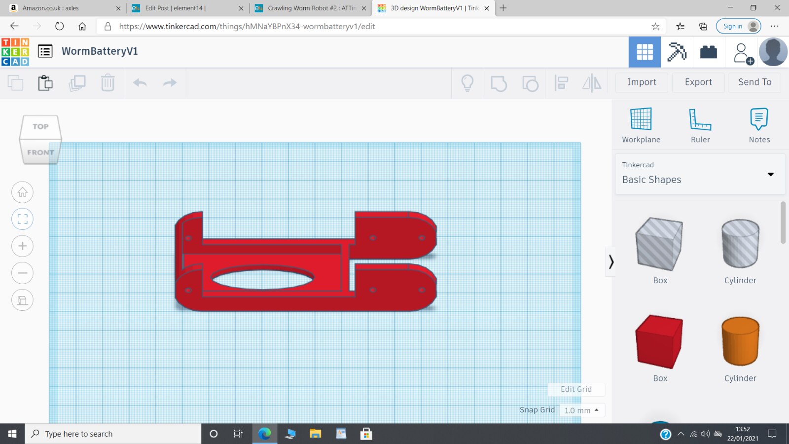
The Battery Chassis
The motor chassis is illustrated below and is essential a lever with a pivot point at the top, a cut out for the battery holder and a hole for the wheel axle.
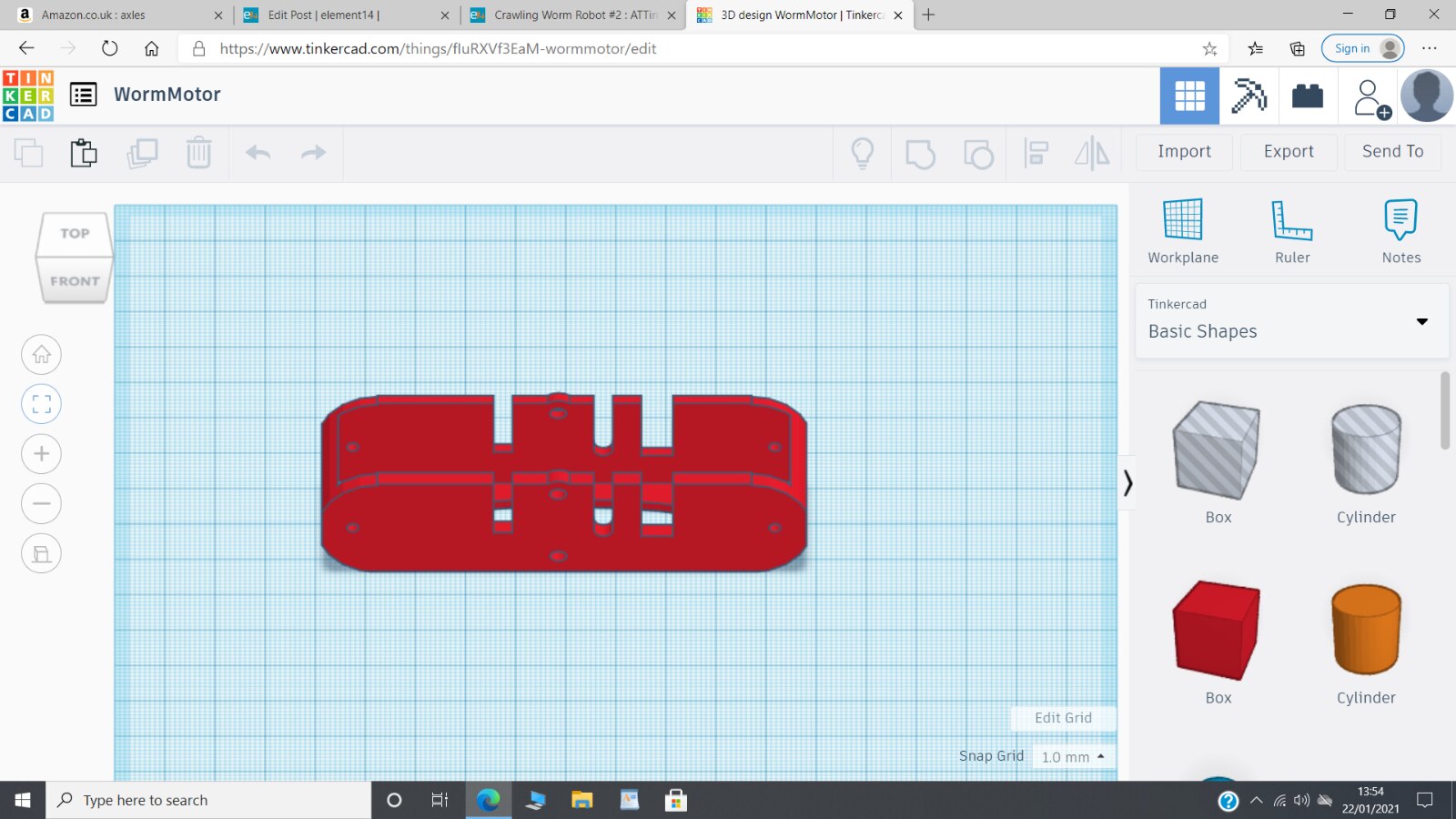
The Motor Chassis
The motor chassis is illustrated below and is another lever with a matching pivot point, slots to enable the DC motor and gearbox unit to just slot in and holes for the axles for the second pair of wheels. This is not a particularly good design as the tall thin parts have a tendency to break off. However, the motor is held in place with bolts so that problem did not affect the functionality.
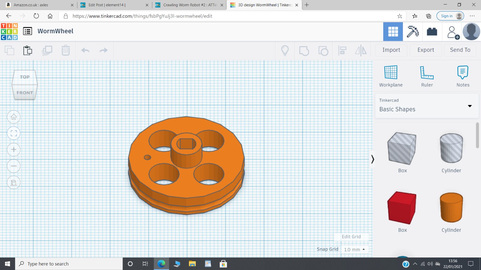
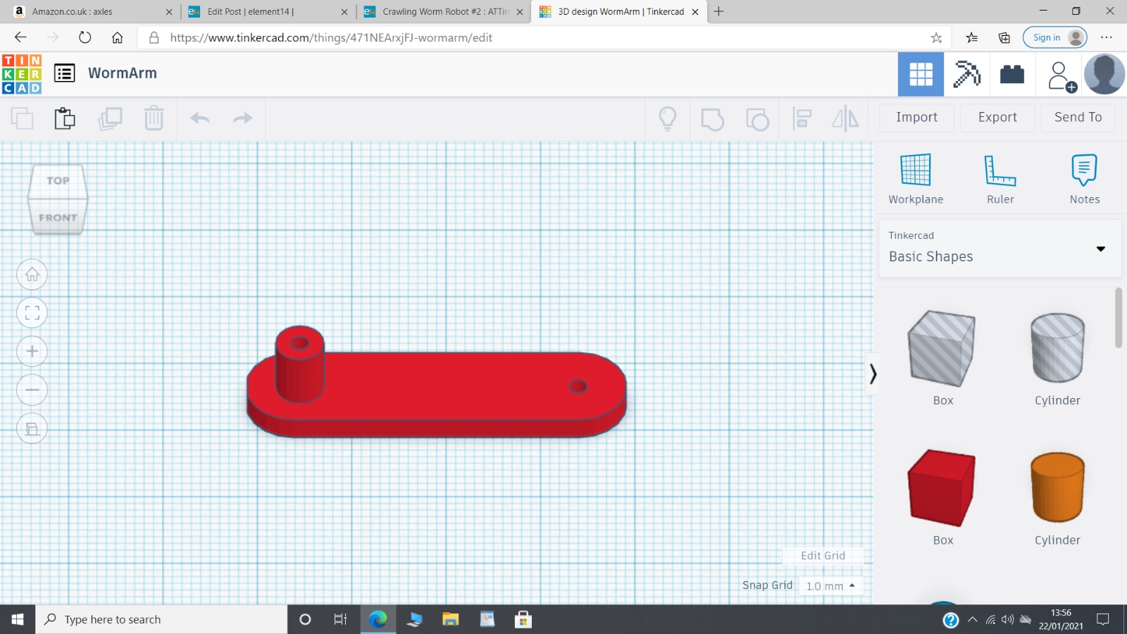
CAM Mechanism
The cam mechanism consists of two parts; a wheel with a centre axle point to fit onto the motor axles with an offset pivot point, and the straight pivot arm, both illustrated below.
Other Parts
I used the small round orange collars from the kit to operate as retainers on the axles, mainly because they worked and I had some and partly because I had the idea that for a future version I would try to eliminate the need for them. Additionally there were the axles and wheels, both of which I used from the kit. I have purchased axles so I can replace these if needed. I know that I can make wheels with the 3D printer so I have left that part for a later time.
Working Without An Elastic Band
I wasn't entirely sure what function the elastic band played that was used in the original kit, so for a first experiment I did not include it. A video showing the worm robot operating without an elastic band is given below.
From this experiment it can be seen that the elastic band must play an important part and I believe that it is needed to provide some additional resistance in one direction, so that the worm robot will move forward. Otherwise, if the two main chassis parts of the worm mechanism have an equal mass then the robot will just bob up and down, as illustrated in the previous video. Adding an elastic band creates the conditions for forward movement as illustrated in the following video
There does seem to be some problem now which may be that the extra resistance introduced by the elastic band just seems to tip the worm robot into a locked position. Or, it may be that the batteries are somewhat exhausted but I did check them before inserting them. It is more likely that I have made a small change to a dimension somewhere and that has just moved the operating point of the robot when extended into some sort of latched state. I will have a closer look at what might be causing this but I suspect that the cam arm may just be a little bit too long. A slightly small version might solve this problem.
All in all, I am pleased with what I have created. The mechanism is much more rigid and it does use fewer parts. Once I can work out what is causing the latching situation then I think I will have a satisfactory chassis.
The Next Step
I now want to try and control more explicitly the angle of the two main parts of the chassis, as well as the speed at which they move. I could add a rotation sensor of some kind but that all seems a bit too complicated. Instead, I will see if I can replace the DC motor with a micro servo motor. If the servo motor is powerful enough I will be able to remove the cam mechanism completely, but have direct control of the angle of the chassis parts and their speed of movement. It will then be much easier to experiment to find the optimum size of the main chassis parts.
Dubbie
Top Comments