


A year ago, the DAC8775 was the subject of the Quad-Channel, Analog Output Module RoadTest. My element14 friend DAB was not impressed by the EVM and its software. I asked if he wanted to trade the board for another evaluation module, and he did. After some hick-ups with post services, the evaluation kit for the DAC is finally in my hands.
My review will be different than the official reviews, because I don't have the device to connect the EVM to USB. I will use SPI to talk to the device instead of the kit's GUI. Maybe this will help future designers to control the device. There are very few code examples available. |

The setup below didn't work for me, most likely because I failed to set up the correct SPI mode (clock polarity and phase) on the Bus Pirate . I'm doing everything over again in a new blog where I use a Hercules microcontroller. I know the SPI module better on that family. spoiler alert: that was successful. |
Test Setup
I'm using a Bus Pirate to generate the SPI traffic. My logic analyser is a Papilio Pro FPGA dev board.
As you can see, everything is bodged together somewhat. But as a lab setup it will do.

The Bus Pirate's 4 SPI pins are connected to the SPI lines of the EVM.
The AUX pin drives the ^RESET.
The analog VPU input reads the ^ALARM signal.
You'll see the Bus Pirate's SPI commands later. But let's review the reset and alarm functions.
The reset signal is connected to AUX.
On the pirate, you can reset the DAC by pulling the reset low for a moment.
Here's the command:

To check the status of the alarm pin, execute this:

First SPI Communication
The Bus Pirate needs to be set up correctly for the DAC.
The speed isn't important because the DAC accepts from slow to very fast. I've selected a speed that's easy to capture on the logic analyser.

First I do a soft reset of the DAC.
The register is 0x01, and the 16 bit data command for a reset is 0x0001
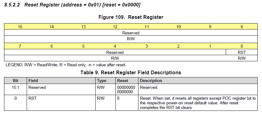

Then I do a read of register 0x02. Why register 2? Just random. I want to check if I can send a command and get data back.
To read a register, you have to set the first bit of the address to 1.
0x02 = 0000 0010 => 1000 0010 = 0x82.
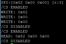
So to read the register 2, I have to send address 0x82, and then 16 bits of random data. The next 24 SPI clock pulses will return the address again, and the value of the register 0x02:

The second train of 3 * 8 bits is to generate the clock pulses that allow the DAC to reply.
I could also have used the command [r:3]. That also generates 24 clocks and returns the data on MISO to the console.
The [ ] pairs generate the chip select signals. According to the spec, the CS has to bump between the command and read. That's why the data is split in two blocks ([0x82 0x00 0x00] [0x00 0x00 0x00]).
Here's the traffic on the logic analyser:

Here's the same example, but I use the Bus Pirate's Read command to generate the 24 read pulses. The advantage is that you actually see the returned data on the console:
I know it's all still a bit fuzzy, but I learn as I go. In perspective of the difficulties I had to go through to get this far, the blog looks structured  .
.
Top Comments