


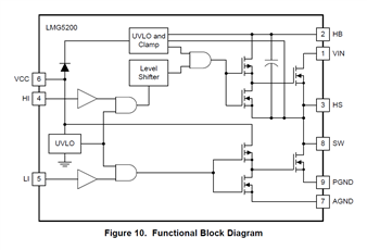
It doesn't have to be silicon all the time. I have a Gallium-nitride device here at the Cumps lab that I'm going to try out. In some high voltage, high power designs, GaN FETs have advantages over Si. On the other hand they are also more difficult to drive.
The chip that I have contains a built-in smart GaN FET driver. That takes away the complexities of driving the power stage correctly. We're covering fairly new technology here. The documents are still marked technology preview. I received them from TI after attending a GaN seminar and answering right on the quiz.
In this post I'm building a PWM deadband generator with a Hercules LaunchPad.
|
PWM with Deadband
To drive our GaN half-bridge, we need two complementary PWM signals.One to drive the upper FET, the other to drive the lower FET.
When one is high, the other has to be low. The worst thing that can happen to a half-bridge is that both FETs are conducting. So we have almost covered that.
Almost, because we need more. For a tiny amount of time during switching, we have to take care that none of the FETs are on - the Dead Time or Deadband.
For an explanation of Dead Time, check the previous article in this series.
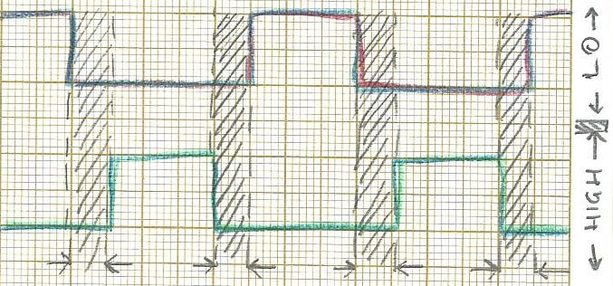
My goal in today's blog is to create that signal with a Hercules LaunchPad PWM module. This is the signal we're after - the hatched areas indicate where both signals (and both FETs) should be off:
Each PWM module of the Hercules controller has a pair of outputs (A and B) that are tied together. They act together, and can be used to generate tightly coupled signals.
By default, the B signal is the inverse of A. When A is high, B is low and vice versa. But you can change that.
One of the things you can change is introduce a delay in the rising edge and the falling edge. That's what we're looking after.
Both signals should have a delay on their rising edge, so that that edge only happens at a given time after the counterpart's falling edge.
If we manage to do that (and we will  ), we have what we need. A set of signals that are each other's compliment, but have a gap between one switching off and its partner switching on.
Two Lines of Code
We configuring the PWM module with HALCoGen, the visual setup application.
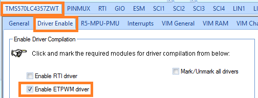
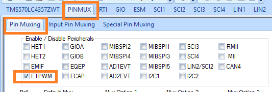
Our first task is to enable drivers, pin multiplex and timer settings.
Driver:
Mux:
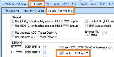
Additional clock Mux config
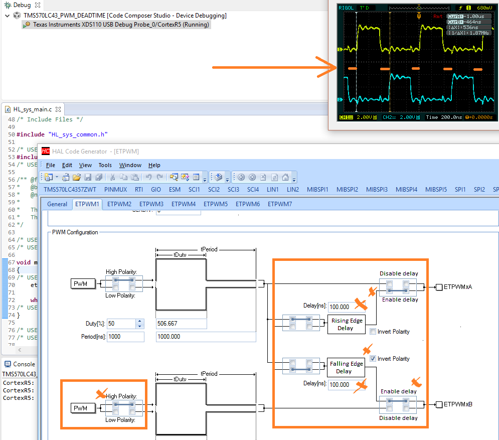
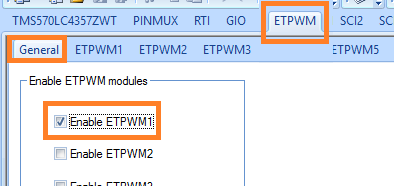
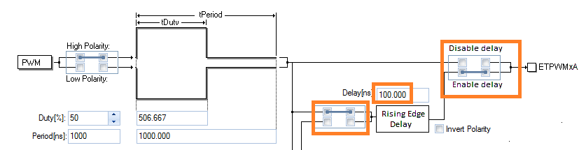
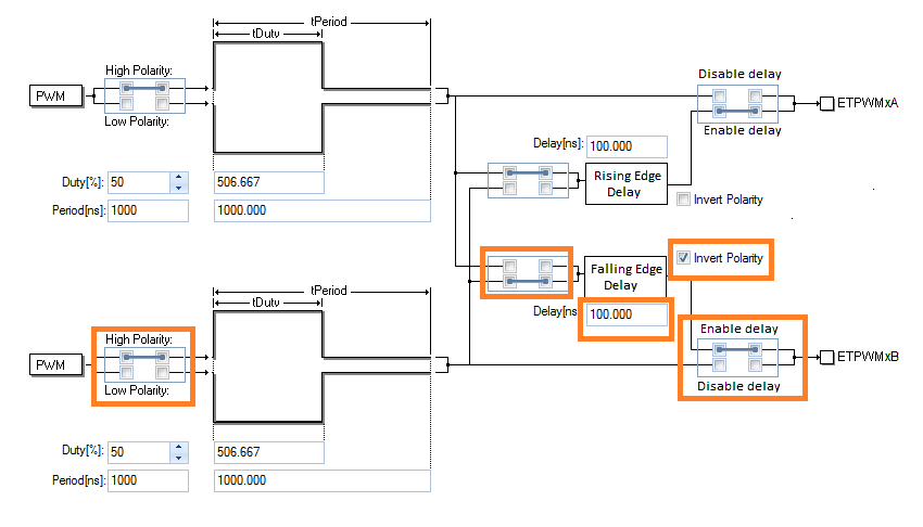
In the PWM tab, we enable the first PWM pair, and set the delays.
Setting the delays needs some more explanation. We have access to two delays, a rising edge and a falling edge delay.
And each of them can be used for one of the two signals, but not both.
So we can't just define a rising edge delay for both channels.
Here's how we get around that situation:
- For the A signal, all is simple, we define the rising edge delay, and route the A signal through that:
- For signal B, it's a bit more tricky. Because we've already used the Rising Edge Delay for signal A, it isn't available for B.
But we still have the Falling Edge Delay available. And we can invert our signal at the begin and the end of its route.
So if we invert signal B by selecting High Polarity (and it becomes identical to signal A at input), then enable Falling Edge Delay, and invert the signal again at the output (Invert Polarity checkbox),
we have sneakingly achieved what we wanted. The Falling Edge becomes the Rising Edge after the last inversion, and we now have two opposite signals, each with their Rising Edge delayed. Win!
The Result
On the oscilloscope, you can see the output of both PWMs. I've added a math A+B signal to show that there's a time where both signals are low. The Deadband.

Fig. 3: Bart Simpson looking over the wall
In this article, I've exaggerated the times to make everything more visible. To drive the LMG5200, we'd choose delays around 6 or 7 ns.
All parameters are runtime configurable. So we can change PWM frequency, duty cycle and delays from firmware. Each can be changed without impacting the other parameters. Full control, anyone?
And as promised, the 2 lines of code needed to make this work:
#include "HL_etpwm.h"
     etpwmInit();
Top Comments