element14 Community
element14 Community
    Register Log In
  • Site
  • Search
  • Log In Register
  • Members
    Members
    • Achievement Levels
    • Benefits of Membership
    • Feedback and Support
    • Members Area
    • Personal Blogs
    • What's New on element14
  • Learn
    Learn
    • eBooks
    • Learning Center
    • Learning Groups
    • STEM Academy
    • Webinars, Training and Events
  • Technologies
    Technologies
    • 3D Printing
    • Experts & Guidance
    • FPGA
    • Industrial Automation
    • Internet of Things
    • Power & Energy
    • Sensors
    • Technology Groups
  • Challenges & Projects
    Challenges & Projects
    • Arduino Projects
    • Design Challenges
    • element14 presents
    • Project14
    • Project Groups
    • Raspberry Pi Projects
  • Products
    Products
    • Arduino
    • Avnet Boards Community
    • Dev Tools
    • Manufacturers
    • Product Groups
    • Raspberry Pi
    • RoadTests & Reviews
  • Store
    Store
    • Visit Your Store
    • 'Choose another store...'
      • Europe
      •  Austria (German)
      •  Belgium (Dutch, French)
      •  Bulgaria (Bulgarian)
      •  Czech Republic (Czech)
      •  Denmark (Danish)
      •  Estonia (Estonian)
      •  Finland (Finnish)
      •  France (French)
      •  Germany (German)
      •  Hungary (Hungarian)
      •  Ireland
      •  Israel
      •  Italy (Italian)
      •  Latvia (Latvian)
      •  
      •  Lithuania (Lithuanian)
      •  Netherlands (Dutch)
      •  Norway (Norwegian)
      •  Poland (Polish)
      •  Portugal (Portuguese)
      •  Romania (Romanian)
      •  Russia (Russian)
      •  Slovakia (Slovak)
      •  Slovenia (Slovenian)
      •  Spain (Spanish)
      •  Sweden (Swedish)
      •  Switzerland(German, French)
      •  Turkey (Turkish)
      •  United Kingdom
      • Asia Pacific
      •  Australia
      •  China
      •  Hong Kong
      •  India
      •  Korea (Korean)
      •  Malaysia
      •  New Zealand
      •  Philippines
      •  Singapore
      •  Taiwan
      •  Thailand (Thai)
      • Americas
      •  Brazil (Portuguese)
      •  Canada
      •  Mexico (Spanish)
      •  United States
      Can't find the country/region you're looking for? Visit our export site or find a local distributor.
  • Translate
  • Profile
Personal Blogs
  • Members
  • More
Personal Blogs
Legacy Personal Blogs How Equalization Works in 10x Passive Probes
  • Blog
  • Documents
  • Mentions
  • Sub-Groups
  • Tags
  • More
  • Cancel
  • New
Blog Post Actions
  • Subscribe by email
  • More
  • Cancel
  • Share
  • Subscribe by email
  • More
  • Cancel
Group Actions
  • Group RSS
  • More
  • Cancel
Engagement
  • Author Author: caroline_teledynelecroy
  • Date Created: 13 Feb 2019 8:56 AM Date Created
  • Views 962 views
  • Likes 6 likes
  • Comments 1 comment
  • probes
  • oscilloscope
  • teledynelecroy
  • teledyne
  • equalization
  • high pass filter
  • lecroy
  • passive probe
  • low-pass filter
Related
Recommended

How Equalization Works in 10x Passive Probes

caroline_teledynelecroy
13 Feb 2019

We've been discussing 10x passive probes and their inner workings; our last post covered all the ways in which a 10x passive probe is apt to be a liability. They'd be basically unusable for any measurements at all but for one attribute: their equalization circuit (Figure 1). Without it, the 10x passive probe makes a pretty good low-pass filter, but the equalization circuit counters that with a high-pass filter to balance things out.


image

Figure 1: The adjustable equalization circuit on the oscilloscope end of the coaxial cable compensates for the 10x passive probe's inherent low-pass filter characteristics


Referring again to Figure 1, there's a 9-10 pF bypass capacitor in parallel with the 10-MΩ input impedance at the tip of the probe. High frequencies will pass through the capacitor, and they'll also see the capacitance at the oscilloscope end of the probe cable. The combination of the low-pass response of the series resistor and shunt capacitance to ground and the high-pass response of the compensation capacitor results in a flat, high-bandwidth response overall.


We want the time constants for the high-pass filter and low-pass filter to be matched so that their pole frequencies are the same; that's what gives our 10x passive probe its overall flat frequency response. If there's too much high-pass filtering, we'll have a peak response, and if there's not enough, we'll have a low-frequency response. We're looking for just the right balance.


That's why the adjustable capacitor, which is typically found at the end of the cable near the coaxial connector, enables us to change that capacitance so that the time constant for the capacitor and resistor at the oscilloscope input is the same as that for the 9-MΩ resistance and capacitance at the business end of the probe. Once we match those time constants, we achieve the flat, uniform frequency response we want to see.


image

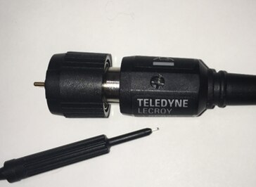
Figure 2: This trimmer capacitor is the key to flattening the probe's frequency response


image

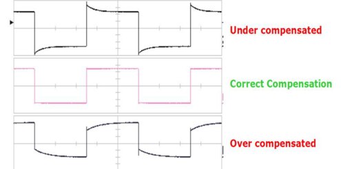
Figure 3: Shown are examples of under-compensation, over-compensation, and proper compensation using the probe's trimmer capacitor


That little adjustment trimmer at the end of the 10x passive probe's cable (Figure 2) adjusts that equalization circuit. Here's how to get things squared away: Plug your probe into the oscilloscope's CAL output on the front panel. That output gives you a fast-edge, clean square wave. You want to adjust that trimmer capacitor until you see a signal on your oscilloscope's display that looks like the one at center in Figure 3. If it looks like either of the other two traces shown, you've not yet matched the time constants of the two filter circuits. You can find more detail about this trimmer adjustment here.


In terms of performance of the 10x passive probe, at frequencies above about 1 kHz the input impedance is mostly made up of that 9-10 pF capacitance. At low frequencies, we'd see the 9 MΩ of the series resistance plus the 1 MΩ of the oscilloscope's input impedance, but there's that 10-pF capacitance shunting that resistance. Thus, the impedance we see looking into the probe is equivalent to about 10 pF, which means that the impedance will drop off as we go higher in frequency. At DC, it's a 10-MΩ input, but it looks like a capacitive impedance at higher frequency. So it's important to take that into account when using the probe.


image

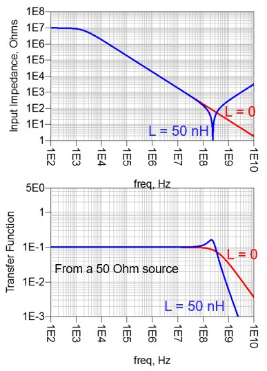
Figure 4: Input impedance and transfer function plots for a 10x passive probe


Another complication is the potential for loop inductance between the signal and return paths. The amount of inductance depends on how we make the connection, but it will have an impact on bandwidth. The L and C result in a series LRC response as seen at the probe tip, which will show up as an impedance dip at higher frequencies and in the transfer function (Figure 4).


We've built what is essentially a two-pole low-pass filter that has some peaking in its response, which is why, if there's some inductance in the return path, we'll see some peaking in the hundreds of MHz range. If our source impedance of the DUT is 50 Ω, the nominal drop in transfer function will be flat with a -20 dB attenuation with a -3 dB drop from the passband region at a couple hundred MHz.


It's important to bear in mind that the input impedance is capacitive as we go to higher frequencies, which ultimately limits the bandwidth to the hundreds of MHz range. Any additional inductance in the tip will further decrease the bandwidth and potentially introduce ringing. This is why we always want low inductance in the tip.


We'll continue exploring the performance of the 10x passive probe in an upcoming post.


Previous posts in this series:

Putting Probes in Perspective

Secrets of the 10x Passive Probe

  • Sign in to reply

Top Comments

  • jc2048
    jc2048 over 4 years ago +3
    Thank you for posting this - very nicely done. I've read the explanation before a couple of times but this is the first time I've seen it supported by the plots you show. Although in theory we can all…
Parents
  • jc2048
    jc2048 over 4 years ago

    Thank you for posting this - very nicely done.


    I've read the explanation before a couple of times but this is the first time I've seen it supported by the plots you show. Although in theory we can all work out the way the impedance at the input varies with frequency, the plot really does emphasise how the capacitive reactance causes it to drop with frequency. At 1MHz we essentially have a 20k probe and at 10MHz a 2k one, which is a long way from the 10M that we all imagine when we first start out and are new to electronics. It's easy to see from the graph how a 'scope probe can have an effect on something like a sensitive analog oscillator circuit, even at frequencies of a few hundred kilohertz.


    It's also useful seeing where the effect of the ground lead inductance comes into play.


    Looking forward to hearing your explanation of the 'Very special cable'.

    • Cancel
    • Vote Up +3 Vote Down
    • Sign in to reply
    • More
    • Cancel
Comment
  • jc2048
    jc2048 over 4 years ago

    Thank you for posting this - very nicely done.


    I've read the explanation before a couple of times but this is the first time I've seen it supported by the plots you show. Although in theory we can all work out the way the impedance at the input varies with frequency, the plot really does emphasise how the capacitive reactance causes it to drop with frequency. At 1MHz we essentially have a 20k probe and at 10MHz a 2k one, which is a long way from the 10M that we all imagine when we first start out and are new to electronics. It's easy to see from the graph how a 'scope probe can have an effect on something like a sensitive analog oscillator circuit, even at frequencies of a few hundred kilohertz.


    It's also useful seeing where the effect of the ground lead inductance comes into play.


    Looking forward to hearing your explanation of the 'Very special cable'.

    • Cancel
    • Vote Up +3 Vote Down
    • Sign in to reply
    • More
    • Cancel
Children
No Data
element14 Community

element14 is the first online community specifically for engineers. Connect with your peers and get expert answers to your questions.

  • Members
  • Learn
  • Technologies
  • Challenges & Projects
  • Products
  • Store
  • About Us
  • Feedback & Support
  • FAQs
  • Terms of Use
  • Privacy Policy
  • Legal and Copyright Notices
  • Sitemap
  • Cookies

An Avnet Company © 2023 Premier Farnell Limited. All Rights Reserved.

Premier Farnell Ltd, registered in England and Wales (no 00876412), registered office: Farnell House, Forge Lane, Leeds LS12 2NE.

ICP 备案号 10220084.

Follow element14

  • X
  • Facebook
  • linkedin
  • YouTube