element14 Community
element14 Community
    Register Log In
  • Site
  • Search
  • Log In Register
  • Members
    Members
    • Benefits of Membership
    • Achievement Levels
    • Members Area
    • Personal Blogs
    • Feedback and Support
    • What's New on element14
  • Learn
    Learn
    • Learning Center
    • eBooks
    • STEM Academy
    • Webinars, Training and Events
    • Learning Groups
  • Technologies
    Technologies
    • 3D Printing
    • Experts & Guidance
    • FPGA
    • Industrial Automation
    • Internet of Things
    • Power & Energy
    • Sensors
    • Technology Groups
  • Challenges & Projects
    Challenges & Projects
    • Design Challenges
    • element14 presents
    • Project14
    • Arduino Projects
    • Raspberry Pi Projects
    • Project Groups
  • Products
    Products
    • Arduino
    • Dev Tools
    • Manufacturers
    • Raspberry Pi
    • RoadTests & Reviews
    • Avnet Boards Community
    • Product Groups
  • Store
    Store
    • Visit Your Store
    • 'Choose another store...'
      • Europe
      •  Austria (German)
      •  Belgium (Dutch, French)
      •  Bulgaria (Bulgarian)
      •  Czech Republic (Czech)
      •  Denmark (Danish)
      •  Estonia (Estonian)
      •  Finland (Finnish)
      •  France (French)
      •  Germany (German)
      •  Hungary (Hungarian)
      •  Ireland
      •  Israel
      •  Italy (Italian)
      •  Latvia (Latvian)
      •  
      •  Lithuania (Lithuanian)
      •  Netherlands (Dutch)
      •  Norway (Norwegian)
      •  Poland (Polish)
      •  Portugal (Portuguese)
      •  Romania (Romanian)
      •  Russia (Russian)
      •  Slovakia (Slovak)
      •  Slovenia (Slovenian)
      •  Spain (Spanish)
      •  Sweden (Swedish)
      •  Switzerland(German, French)
      •  Turkey (Turkish)
      •  United Kingdom
      • Asia Pacific
      •  Australia
      •  China
      •  Hong Kong
      •  India
      •  Korea (Korean)
      •  Malaysia
      •  New Zealand
      •  Philippines
      •  Singapore
      •  Taiwan
      •  Thailand (Thai)
      • Americas
      •  Brazil (Portuguese)
      •  Canada
      •  Mexico (Spanish)
      •  United States
      Can't find the country/region you're looking for? Visit our export site or find a local distributor.
  • Translate
  • Profile
Personal Blogs
  • Members
  • More
Personal Blogs
Legacy Personal Blogs How I started with my DIY and hacking projects? (LED Sky project - more pics to come)
  • Blog
  • Documents
  • Mentions
  • Sub-Groups
  • Tags
  • More
  • Cancel
  • New
Blog Post Actions
  • Subscribe by email
  • More
  • Cancel
  • Share
  • Subscribe by email
  • More
  • Cancel
Group Actions
  • Group RSS
  • More
  • Cancel
Engagement
  • Author Author: matija.martinec
  • Date Created: 2 Jan 2015 4:42 PM Date Created
  • Views 407 views
  • Likes 1 like
  • Comments 8 comments
  • logic
  • digital
  • to
  • project
  • diy
  • led
  • 74199
  • lights
  • how
  • electronics
  • hacking
Related
Recommended

How I started with my DIY and hacking projects? (LED Sky project - more pics to come)

matija.martinec
matija.martinec
2 Jan 2015

This post is mainly going to discuss how I have started my projects like my LED sky, 5x5x5 RGB cube (Currently does not exist because it was squished flat on the party...) etc.


Let's use the LED sky as our example :

When you want to do a project you need an IDEA!! No idea no project. I got my idea from a local mall that had a huge ceiling with bunch of LED's in it that were glowing like stars. Normally I did even consider that as my future project but I decided to do it when my sister said that shed like something like that.


So as a "good brother" I started doing some ideas; firstly I considered doing it with arduino which was my main source of ideas and projects. I designed few shields that I would etch in my school, but just before i decided to make them I consulted my teacher from Digital Logic who gave me idea to consider using 8-bit shift register 74199N which depending on how you connect it could make bnch of led's glow in different order, so I figured it would me much much cheaper than using my one and only arduino I had, since i can't really buy arduinos so easily. So the 1st point is, ALWAYS, but always consult other people that could improve your design and reduce even the cost of your projects, I had my teacher, but you, you have the whole Element14 community!, use that!


This project could be placed in the category of medium-hard projects, but not for the complexity to assemble it, but to learn how the logic behind the chip works so you can use that to the maximum. What I'm trying to say is that you should always learn and research before you start doing something, if you spend just that much more time on learning you will save hours and hours of troubleshooting after if your circuit does not work.


First I settled down to try and make the circuit in MultiSim 12, which is a EWB (electronics workbench) program in which you can test your designs and see if and how they work (I highly recommend it). After about few days trying how and why it works I made the schematic :

image

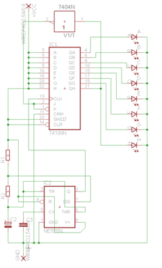
As you can see it is a load of mess!! I didn't even make the right power connections (instead of using the correct VCC and GND connectors I used troughole pins as power which does not connect with the hidden power pins on the 74199 - you can see that there is no VCC and GND on the chip)

Next I try to make the PCB (just used auto route) :

image

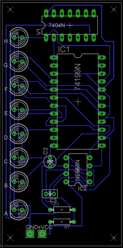
The first problem is that the routes are going behind the connectors for LED groups (connectors are just LED,s on the PCB), second problem it isn't very well designed, and because of the faulty power connections in the schematic the power for the chips was not connected and I did not notice it.

Then I was eager to etch the PCB in my school. When I came and asked my teacher if I can do it he said that we didn't have any more etching solution (I was kinda devastated), and it was only a few days before Christmas and I really wanted to make this in time for my sister so she could open it on Christmas eve ( we always open presents on Christmas eve for some random reason).

I knew I had no choice but to make my own PCB on a piece of perforated board. So I started wiring up and ended up with this mess :


image

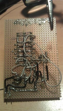
And you guessed it, it DID NOT work! After a few hours of troubleshooting I did fix something but it turns out some LED's light up brighter than the others, then with the multimeter I figured that some outputs from the chip gave around 2.5 and some 3.5 volts maximum. And also the board was working at certain angles because the wires were loosely attached.

So I went and made a yet another board :

(this board is not over yet i had to connect the bases of the drivers(transistors) to the outputs of the chip)image

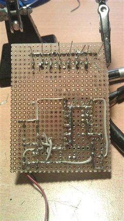
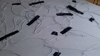
You can see that this board is much nicer than the previous one and it actually worked. So then i had to wire up the sky itself(it was a PAIN IN THE BUTT to wire all of the LED's up) :

image

And I was pleasantly surprised when I found out that it actually works! :

(Here you see that not all of the LED's aren't lit up -- > that is due to the animation of glowing)image

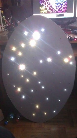
The led's are wired up in this princible

image

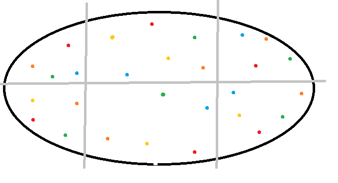
Where each colour represents the different groups of led's (e.g. red - A, orange - B etc.)

When you set the chip to light the led's in an specific order you get the illusion of them glowing randomly.


So this was just dos and do nots of when making projects.

In conclusion :

  • Always start with a detailed plan, do your research thoroughly
  • When creating schematics and PCB's TAKE YOUR TIME, there is nothing worse than figuring you made one connection wrong and when you make the PCB you figure that you have to start all over again
  • When wiring try to imagine different scenarios (layouts) in which you can connect stuff
  • Don't start with ultra ultra hard projects, if you have never done any projects I recommend you to start with a simple 555 timer in astable mode, fun circuit that blinks 2 LED's.

I hope you enjoyed my little bog post of my endeavours to succeed at this project in reasonably small margin of time.

If you have any question leave them in the comments section below I will gladly answer them, and if you liked this post like it


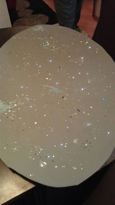
In the end we added just a bit paint :

image

  • Sign in to reply

Top Comments

  • jw0752
    jw0752 over 8 years ago +3
    Hi Matija, I had some time so here is my procedure when working with the perf board assembly. This is just a demonstration that I mocked up. First I decide where I will need trace runs on the board, for…
  • jw0752
    jw0752 over 8 years ago +2
    I enjoyed your post and your detailed description of the problems that crop up in every attempt to make something. Well done and good for you not giving up after the first board. John
  • jw0752
    jw0752 over 8 years ago in reply to matija.martinec +2
    Hi Matija, I always find that it is easier to run a piece of buss wire between the points that I want to connect and then solder it down to the pads on the board. I use a piece that is longer than needed…
  • jw0752
    jw0752 over 8 years ago

    Hi Matija,

    I had some time so here is my procedure when working with the perf board assembly. This is just a demonstration that I mocked up. First I decide where I will need trace runs on the board, for example for power and ground. I then take a piece of #24  buss wire and straighten it. You can easily straighten wire by grabbing the two ends with pliers and twisting it. Here is a before and after of the buss wire.


        imageimage


    I will then take the straightened wire and solder tack it to the end of where I want the trace to go. I am careful not to cover any of the holes that I intend to use. I bend the wire around and I usually tack it again with solder at all the corners. Here is the result of installing the trace. The second picture is the component side of the board at this time.


         imageimage


    If I get too much solder on a point I just use a little wick to tidy it up. Now I will install a few components to show how it works out to have the buss wire there acting as a trace.


         imageimage


    I almost never try to bridge 2 pads with just solder. Usually there is a lead that can be bent down to make the bridge and then be soldered into place. Incidentally, I clip and save all the reasonable length component leads just for the purpose of making traces on the prototype perf boards that I build.

    John

    • Cancel
    • Vote Up +3 Vote Down
    • Sign in to reply
    • More
    • Cancel
  • jw0752
    jw0752 over 8 years ago in reply to matija.martinec

    Hi Matija,

    I always find that it is easier to run a piece of buss wire between the points that I want to connect and then solder it down to the pads on the board. I use a piece that is longer than needed so I can hold it in place and then I clip off the extra after it is soldered into place. This eliminates the need to put so much solder onto the pads that they form a bridge. While not perfect it makes for a slightly neater job and also make a more solid connection.

    John

    • Cancel
    • Vote Up +2 Vote Down
    • Sign in to reply
    • More
    • Cancel
  • matija.martinec
    matija.martinec over 8 years ago in reply to mcb1

    I am actually a lot experienced with soldering because we are doing it every week in school for 4 hours image, and I've been soldering for about 5-6 years now , but the only new experience I had right now was soldering these huge chunks of solder like paths (I was frustrated at first because I could not get the other solder to connect to the previous chunk)

    • Cancel
    • Vote Up 0 Vote Down
    • Sign in to reply
    • More
    • Cancel
  • jw0752
    jw0752 over 8 years ago

    I enjoyed your post and your detailed description of the problems that crop up in every attempt to make something. Well done and good for you not giving up after the first board.

    John

    • Cancel
    • Vote Up +2 Vote Down
    • Sign in to reply
    • More
    • Cancel
  • mcb1
    mcb1 over 8 years ago in reply to matija.martinec

    Matija

    Okay then.

    Can I suggest that technique may be contributing to the issue .

    I'm involved with many schools in soldering a Christmas Tree, and one of the thing we run across is pupils applying the solder onto the iron, rather than to the junction of the board and component.

    This tends to burn off the flux needed to help the solder join the two parts together, and it seems this was the way they were taught.  ( ..... "un-learning" them is the first challenge).


    Adafruit have this excellent tutorial :-

    https://learn.adafruit.com/adafruit-guide-excellent-soldering


    In particular this page shows the right way to apply the solder (and where the pupils have the most problems)

    https://learn.adafruit.com/adafruit-guide-excellent-soldering/making-a-good-solder-joint


    And to reassure you, I've seen techs who have 20 + years experience still have problems soldering .... image


    Mark

    • Cancel
    • Vote Up +1 Vote Down
    • Sign in to reply
    • More
    • Cancel
>
element14 Community

element14 is the first online community specifically for engineers. Connect with your peers and get expert answers to your questions.

  • Members
  • Learn
  • Technologies
  • Challenges & Projects
  • Products
  • Store
  • About Us
  • Feedback & Support
  • FAQs
  • Terms of Use
  • Privacy Policy
  • Legal and Copyright Notices
  • Sitemap
  • Cookies

An Avnet Company © 2023 Premier Farnell Limited. All Rights Reserved.

Premier Farnell Ltd, registered in England and Wales (no 00876412), registered office: Farnell House, Forge Lane, Leeds LS12 2NE.

ICP 备案号 10220084.

Follow element14

  • X
  • Facebook
  • linkedin
  • YouTube