element14 Community
element14 Community
    Register Log In
  • Site
  • Search
  • Log In Register
  • Community Hub
    Community Hub
    • What's New on element14
    • Feedback and Support
    • Benefits of Membership
    • Personal Blogs
    • Members Area
    • Achievement Levels
  • Learn
    Learn
    • Ask an Expert
    • eBooks
    • element14 presents
    • Learning Center
    • Tech Spotlight
    • STEM Academy
    • Webinars, Training and Events
    • Learning Groups
  • Technologies
    Technologies
    • 3D Printing
    • FPGA
    • Industrial Automation
    • Internet of Things
    • Power & Energy
    • Sensors
    • Technology Groups
  • Challenges & Projects
    Challenges & Projects
    • Design Challenges
    • element14 presents Projects
    • Project14
    • Arduino Projects
    • Raspberry Pi Projects
    • Project Groups
  • Products
    Products
    • Arduino
    • Avnet & Tria Boards Community
    • Dev Tools
    • Manufacturers
    • Multicomp Pro
    • Product Groups
    • Raspberry Pi
    • RoadTests & Reviews
  • About Us
  • Store
    Store
    • Visit Your Store
    • Choose another store...
      • Europe
      •  Austria (German)
      •  Belgium (Dutch, French)
      •  Bulgaria (Bulgarian)
      •  Czech Republic (Czech)
      •  Denmark (Danish)
      •  Estonia (Estonian)
      •  Finland (Finnish)
      •  France (French)
      •  Germany (German)
      •  Hungary (Hungarian)
      •  Ireland
      •  Israel
      •  Italy (Italian)
      •  Latvia (Latvian)
      •  
      •  Lithuania (Lithuanian)
      •  Netherlands (Dutch)
      •  Norway (Norwegian)
      •  Poland (Polish)
      •  Portugal (Portuguese)
      •  Romania (Romanian)
      •  Russia (Russian)
      •  Slovakia (Slovak)
      •  Slovenia (Slovenian)
      •  Spain (Spanish)
      •  Sweden (Swedish)
      •  Switzerland(German, French)
      •  Turkey (Turkish)
      •  United Kingdom
      • Asia Pacific
      •  Australia
      •  China
      •  Hong Kong
      •  India
      •  Korea (Korean)
      •  Malaysia
      •  New Zealand
      •  Philippines
      •  Singapore
      •  Taiwan
      •  Thailand (Thai)
      • Americas
      •  Brazil (Portuguese)
      •  Canada
      •  Mexico (Spanish)
      •  United States
      Can't find the country/region you're looking for? Visit our export site or find a local distributor.
  • Translate
  • Profile
  • Settings
Personal Blogs
  • Community Hub
  • More
Personal Blogs
Legacy Personal Blogs Looking at the DMX 512 protocol with a Keysight EDUX1002A scope
  • Blog
  • Documents
  • Mentions
  • Sub-Groups
  • Tags
  • More
  • Cancel
  • New
  • Share
  • More
  • Cancel
Group Actions
  • Group RSS
  • More
  • Cancel
Engagement
  • Author Author: beacon_dave
  • Date Created: 3 Aug 2017 12:27 PM Date Created
  • Views 6341 views
  • Likes 7 likes
  • Comments 6 comments
  • lighting
  • dso
  • oscilloscope
  • rs485
  • keysight technologies
  • edux1002a
  • protocol
  • dmx-512
  • entry_level
Related
Recommended

Looking at the DMX 512 protocol with a Keysight EDUX1002A scope

beacon_dave
beacon_dave
3 Aug 2017

First outing with an entry-level Keysight Technologies Infiniivision  EDUX1002AEDUX1002A digital storage oscilloscope

Keysight EDUX1002AKeysight EDUX1002A


The particular task chosen was to look at the DMX 512 protocol generated from a Chauvet Xpress 512 DMX lighting controller.

https://www.chauvetdj.com/products/xpress-512/


For those unfamiliar with the DMX 512 protocol it is a serial protocol developed back in 1986 and commonly used in the entertainments lighting industry. It most commonly runs on top of the industry standard RS485 serial bus running at a data rate of 250kbps.


The first step was to take a look at a single DMX 512 packet on the scope. The packet starts with a 'break' of >88μs and I decided to use the 'pulse width' trigger mode of the scope to trigger on this pulse. Using the cursors I could measure the duration of the packet which is shown here as around 50.2ms giving a DMX 'universe' refresh rate of around 20Hz.

image


The 'break' is required to be 88μs or more, and on paper is commonly reported as being in the order of 100μs to 200μs. In this case we can see it is significantly greater at around 1ms.

image

In this case I could have increased the pulse width trigger time from 88μs up to around 1ms.


After the 'break' is the 'mark after break' which requires to be a minimum of 4μs in the original spec but 8us in the revised 1990 spec. In this case it is around 17.9ms which appears rather excessive. In some cases this time is increased to make up the minimum packet duration if only a few data frames are being transmitted, however not required here as the payload appears to be the max permitted 512 frames.

image


After the 'mark after break' comes the data payload. This is comprised of a start code followed by up to 512 channel data frames. In this case around 29.4ms.

image


After the channel data comes the 'mark after last channel' at around 1.9ms which then is followed by the 'break' of the next packet.

image


First observations by using the scope to look at the signal are that:

  • the start of packet 'break' is significantly longer than expected
  • the 'mark after break' is significantly longer than expected and which has a significant impact on the overall refresh rate
  • the controller is sending out all 512 channel data frames even though my controller software was only sending data for the first channel


Next step was to look at some of the signal components in more detail. First up we have the start of packet 'break' preceded by the 'mark after last channel'.

image


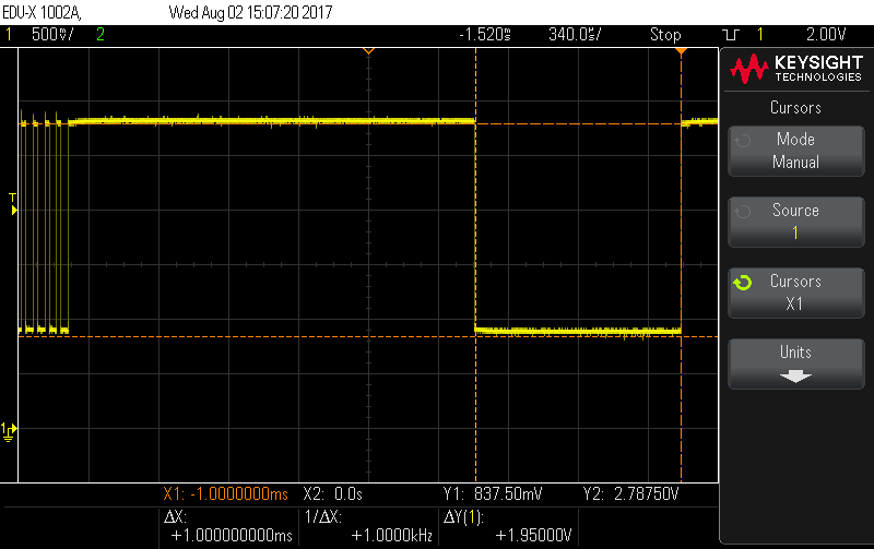
Then there is the 'mark after break'.

image


Then come the data frames. These are 44μs in duration comprising of one low start bit, 8 data bits, and 2 high stop bits. 11bits total each of 4μs duration.


The first is the 'start code'. The most common has a value of 0 which denotes that 'dimmer' data follows.

image


Then come the channel data frames of which there can be 1 to 512.


This is the channel 1 frame showing a data value of 8

image


and channel 1 again showing a value of 85.

image

First low pulse is the start bit, followed by bits 0-7 alternating, followed by 2 high stop bits which merge into the 'mark between frame' idle time.

(In this case bits 0, 2, 4 and 6 are set, 1 + 4 + 16 + 64 = 85)


Here are the first 4 channels showing data values of 2, 4, 16 and 64. The width of each bit is 4μs as expected.

image


In-between each data frame is the 'mark between frame', shown here between the 'start code' and channel 1 as being around 12.7μs.

image


Again, the 'mark between frame', this time between channels 1 and 2.

image

This 'mark between frame' is optional however and the data frame stop bit can be followed immediately by the next data frame start bit.


After the last channel data frame is the 'mark after last channel' shown here as around 1.98ms. Once again this is optional and the last channel data frame stop bit can be followed immediately by the start of packet 'break'.

image


And that concludes the first outing with the  EDUX1002AEDUX1002A scope and a quick overview of the DMX 512 protocol

  • Sign in to reply

Top Comments

  • mcb1
    mcb1 over 8 years ago +4
    Well done. Imagine trying to capture that on an analogue scope without storage It begs the question how did we Engineers manage in the 'old days'. I suspect we had some dedicated test equipment that could…
  • shabaz
    shabaz over 8 years ago +3
    Hi Dave, Great demonstation of the 'scope and the high quality screen-capture capability, and also excellent information on DMX512! I have some DMX-controlled (I suspect DMX512) lights somewhere and I…
  • beacon_dave
    beacon_dave over 8 years ago in reply to shabaz +3
    I get the feeling that the Xmas lights at 'chez Shabaz' could be 'interesting' this year. (Trans-Syberian Orchestra's 'Wizards in Winter' is a popular sync track for this.) Of course it doesn't just have…
Parents
  • mcb1
    mcb1 over 8 years ago

    Well done.

    Imagine trying to capture that on an analogue scope without storage image


    It begs the question how did we Engineers manage in the 'old days'.

    I suspect we had some dedicated test equipment that could break down the protocol for us.


    Cheers

    Mark

    • Cancel
    • Vote Up +4 Vote Down
    • Sign in to reply
    • More
    • Cancel
Comment
  • mcb1
    mcb1 over 8 years ago

    Well done.

    Imagine trying to capture that on an analogue scope without storage image


    It begs the question how did we Engineers manage in the 'old days'.

    I suspect we had some dedicated test equipment that could break down the protocol for us.


    Cheers

    Mark

    • Cancel
    • Vote Up +4 Vote Down
    • Sign in to reply
    • More
    • Cancel
Children
  • beacon_dave
    beacon_dave over 8 years ago in reply to mcb1

    In the 'old days' I seem to recall a lot more external protocol-specific trigger boxes being available on the market (and in electronics magazine project articles), whereas nowadays you have some of the functionality built into the basic scope and then more specific stuff is a licensed add-on option (for the more popular protocols).

    • Cancel
    • Vote Up +1 Vote Down
    • Sign in to reply
    • More
    • Cancel
element14 Community

element14 is the first online community specifically for engineers. Connect with your peers and get expert answers to your questions.

  • Members
  • Learn
  • Technologies
  • Challenges & Projects
  • Products
  • Store
  • About Us
  • Feedback & Support
  • FAQs
  • Terms of Use
  • Privacy Policy
  • Legal and Copyright Notices
  • Sitemap
  • Cookies

An Avnet Company © 2025 Premier Farnell Limited. All Rights Reserved.

Premier Farnell Ltd, registered in England and Wales (no 00876412), registered office: Farnell House, Forge Lane, Leeds LS12 2NE.

ICP 备案号 10220084.

Follow element14

  • X
  • Facebook
  • linkedin
  • YouTube