


This is a follow on from an earlier posting:
I have written this in response to a request from kennethbuenaventura to show how to send 2 or more data items from an Arduino, via Bluetooth and display them on an Android device.
A helpful link to a video by "planetleak" was posted by cams2908:
https://www.youtube.com/watch?v=DkGGilznfG8 but this solution proved to be a little confusing.
In essence, this solution "codes" the readings from 2 analog inputs so that one still reads 0 - 1023 and the other reads 2000 -3023. These coded data items are then transmitted over Bluetooth, to the Android device where they are decoded and displayed separately.
This works, but is confusing because in the Arduino sketch the coding is done by mapping the data, including unnecessarily mapping the first data item as 0, 1023, 0, 1023. Clearly this has no effect.
Thus, in my Arduino sketch I have removed the mapping, leaving the first data item alone and simply adding 2000 to the second data item:
// simulate transmission of 2 changing data items for Android demonstration

const int pot = A0;

void setup()
{
  pinMode(pot, INPUT);
  Serial.begin(9600);
}

void loop()
{
  int potVal1 = analogRead(pot);
  int potVal2 = potVal1/2;              // just to give a different value
  potVal2 = potVal2 + 2000;             //Second value shifted 2000 and 3023
  Serial.println(potVal1);
  delay(500);
  Serial.println(potVal2);
  delay(500);
}
In the Android App, there is more confusion because of the way the decoding is handled.
Firstly, I have simplified, and modified the Android display. I have also added a Bluetooth disconnect function block to the app.
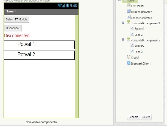
Ignoring the Bluetooth connection and disconnection blocks, which have been show elsewhere, my data processing block looks like this:
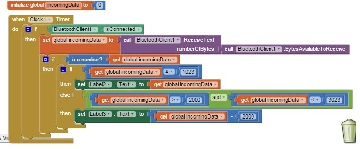
I have used a variable, rather than labels, for the data decoding. The variable is defined, globally, outside of the main code block and initialised to 0.
Once the incoming data string has been captured to the variable "incomingData", it is tested to make sure it is numeric - it will be, most of the time, but there are sometimes glitches in the serial comms or the Bluetooth, which can result in run-time errors.
Assuming that "incomingData" is numeric, it is tested for size: less than 1024 is displayed in Label2; between 2000 and 3023, subtract 2000 and the result is dispalyed in Label3.
Leaving in the test for <= 3023 allows for easy expansion of this solution to more than 2 data items
When I looked at kennethbuenaventura's problem in more depth I appreciated that there was another way of approaching the problem which more closely matched his requirement.
If the data output to serial on the Arduino includes labels, then the Android app merely needs to identify the label and on the basis of the label, display the data appropriately.
If the Arduino sends something like:
LED = 135 assume each data string is followed by CR/LF
LDR = 245
LED = 178
LDR = 465 etc
Then all we need to do in the Android app is look for the sub-strings "LED" and "LDR" within each incoming data string. We can then display the whole data string as text on the appropriate label
Here is a simple Arduino sketch to simulate the suggested serial output:
// Simulate 2 labelled data items and output to serial for Android demonstration
const int pot = A0;
void setup() {
pinMode(pot, INPUT);
Serial.begin(9600);
}
void loop() {
int potVal1 = analogRead(pot);
int potVal2 = potVal1/2; // just to give a different value
Serial.print("LED State = " );
Serial.println(potVal1);
delay(600);
Serial.print("LDR Value = " );
Serial.println(potVal2);
delay(600);
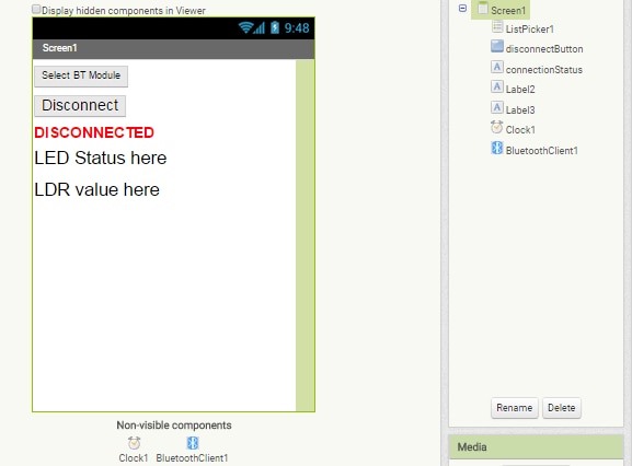
}Here is the screen design from App inventor and below that are the code blocks to process the data strings:
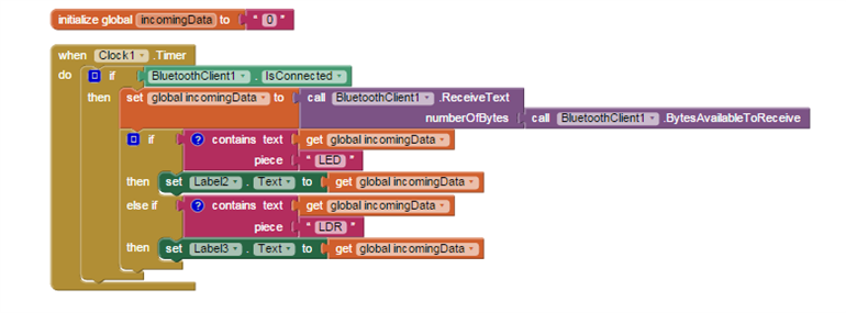
Again, the incoming data string is captured to the variable, which is initialised to "0", but this time we are handling it as text and so there is no need to test to see if it is a number - indeed, it isn't!!
The data string is first tested to see if it contains the sub-string "LED". If so, it is displayed in Label2 and processing ceases. If "LED" is NOT found (else if), then the data string is tested for "LDR", and if found, displayed in Label3. Processing then ceases.
I hope that both of these examples are clear.
I have attached the .aia files to load into App Inventor for both of the example Arduino apps
Top Comments