


Introduction
NIC stands for Negative Impedance Converter. It's one particular circuit configuration that can exhibit the
phenomena of negative resistance. I'm going to look at that first and then, once we've done that, I'm going
to use a pair of them to power a rather curious oscillator circuit due to Chua (the fun bit).
An Op Amp Negative Impedance Converter
As I'm sure you all know, a simple passive resistor has a property called resistance. The resistance is the
constant of proportionality between the current through the resistor and the voltage across the resistor and
is always positive. If we reverse the voltage, the current also reverses and so the signs cancel, leaving us
still with a positive value for the resistance. Plotted as voltage against current, the resistance is the slope of
the curve. It's not too difficult to imagine a circuit where the current falls as the voltage increases and that's
what a NIC does.
Here it is, as I've got it in the simulator.
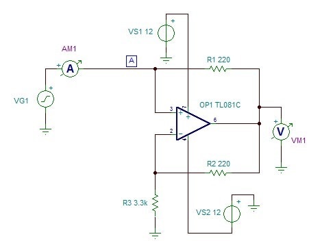
Unusually, it has just one port. Most circuits we look at generally have two or more ports, at least an input
and an output, but this circuit has just one; the port serves as both the input and the output. In that, it's similar
to passive components such as resistors, capacitors, and inductors, except that one side of the port connects
to ground.
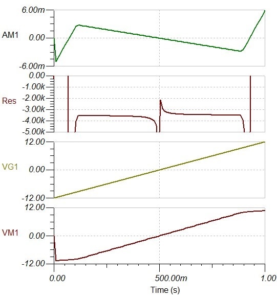
I'm driving the input with a very slow ramp between the negative supply voltage and the positive supply voltage
so we can see how it behaves. The resistance curve has been computed by the post-processor, after running
the simulation, by using Ohm's Law on the voltage and current measured at the input. Over quite a wide central
range, as the input voltage increases, we can see that the current falls and the computed value for the resistance
shows a value of somewhere between -3k and -4k. Not too surprisingly, that starts to fail when the op amp output
gets to within a couple of volts of either supply rail. [The messy bit in the middle is the post-processor not liking
the very small values around zero.]
Understanding how it works, in a qualitative way, is quite simple (not always the case, even with seemingly
simple op amp configurations, once we go beyond the standard amplifier circuits - the Howland current pump,
for one, seems to be messy to explain without using equations as I've just discovered). Negative feedback will
cause the amplifier to drive the output (if it is able to do that) in such a way as to bring the difference in
potential between the op amp inputs to a very small value. For an ideal op amp, with infinite gain, that difference
would be zero but for a real amplifier there has to be a small voltage there, though for this purpose we can take
it as being zero. So we can quickly see that the voltage at the circuit input will be the same as the voltage at the
top of the resistor to ground (R3). That voltage defines the current through the resistor. Since the op amp has a
high impedance input, that same current also flows in the resistor from the op amp output (R2). As the resistor
(R1) from the output to the non-inverting input has the same value as the one to the inverting input and there
is the same voltage across it, there will also be the same current flowing in that one. That current flows out
of the input to the circuit. In short, the NIC applies the voltage from the input to the resistor and then mirrors
the negative of its current back to the input. Looking into the input it then seems as though we are seeing the
negative of the resistance R3. [An obvious way to vary the circuit would be to change the ratio between the two
feedback resistors to something other than 1:1 and use that to scale the resistance.]
Whilst the analysis was for a resistor, if we had a capacitor or inductor in place of the resistor, the circuit would
similarly attempt the negative of the current and by doing so convert a pure capacitor into an inductor or a pure
inductor into a capacitor, though we might need to look quite carefully at how the op amp behaved stability-wise
with a reactive component, depending on the resistors doing the feedback.
Let the Lord of Chaos Reign
Now for the fun part.
I didn't mention it in the previous section but another feature of a negative resistance is that it no longer
dissipates power in the same way as a passive resistor does. That's because P = IV now gives a negative result.
That means it can power an oscillator circuit. Of course the power doesn't come out of thin air; the source is
the power supply, via the op amp output, but we can treat the NIC circuit as behaving as though it were a simple
negative resistor.
Chua published a model that he claimed exhibited chaotic behaviour. He said that it was necessary to have
at least three energy storing components and invented a component he called the Chua diode to power them.
The 'diode' was a combination of a negative resistor to power the oscillations and a non-linear element that
would act as a limiter (I'm not particularly clear about this, but I think the non-linear element positions the
attractors and prevents the circuit running off to one or other rail and just sitting there).
Here's the circuit I used for these experiments.
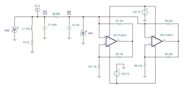
It derives from one published in An Analog Electronics Companion [2], though I've adapted it a little for the
particular op amps and inductor that I had to hand. The resistor shown in series with the coil (R7) is really
just that of the winding resistance: I could have included it as one of the coil's hidden parameters instead
but thought it would be better to have it there on the schematic. The resistance leads to damping of the
oscillations and will have an effect on whether the oscillator oscillates at all. The XY plot on the oscilloscope
I did by measuring the points I've labelled 'A' and 'B'. Hamilton points out in his book that there are also
interesting XY plots to be seen if you plot one of the voltages against the currents that circulate (easy to
view in the simulator, but a bit more challenging in the physical circuit).
Here is the circuit built on a breadboard
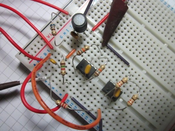
and here is the result displayed XY on an oscilloscope
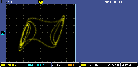
I found that the most critical component was the resistor (R8) linking the two capacitors together. Too high
a value and not enough energy will get to the coil and capacitor (L1 and C1), from the NICs, to maintain
the oscillation. Too low a value, and the two capacitors (C1 and C2) couple tightly with the coil and the
whole thing oscillates at a single frequency, with just a phase shift between the two capacitors, giving rise
to a simple ellipse on the XY plot. Somewhere between, there's a point where the two sides are loosely
coupled and just lightly influence each other and that's where the chaotic behaviour occurs. I used a fixed
resistor of 680R, in series with a 1k pot, so that I could adjust it to find a good value. Note that it is very
unlikely to be the same as whatever value you find you need to get it going in the simulator.
A couple of practical points if you want to try to get it working in the simulator. I found that I had to force
the node I've labelled 'A' to zero volts at the start in order to get it to oscillate. I also had to load the analysis
parameter set that is specifically for oscillators, it didn't work with the default set.
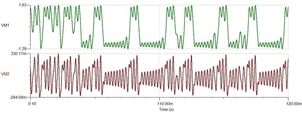
Here are the waveforms that a transient analysis gives
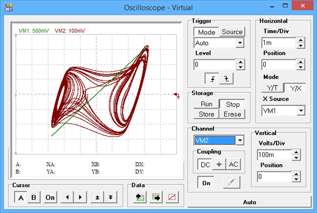
And here it is on the virtual oscilloscope that you can access from the 'T&M' menu
So why did Hamilton use two NICs rather than one? As far as I can see, the answer lies in the feedback
resistors. By having high values for one of the NICs, he engineers a situation where the negative
resistance for that NIC only happens over a restricted part of the range [because the op amp output
runs out of voltage to drive it]. Once that is put in parallel with the other NIC, that then gives the non-linear
response that Chua required in addition to the negative resistance.
The reason for having to have at least three energy storing elements is that if there were only two
elements we wouldn't get the trace crossing - in this case, the XY plot is a projection of a trajectory
in a 3-D space.
Final thought: the simulation is totally deterministic and the traces are the same each and every time.
Chaotic behaviour isn't the same thing as randomness. However, the real circuit is naturally sensitive
to noise and is evidently being thrown around a good deal. The general form, with the orbits traced
around the two attractors, are very similar but the simulation won't ever match the the real results.
I don't claim any particular expertise with all of this (chaos or NICs) and wouldn't have got to a working
circuit without the help of Hamilton's book. If anyone out there understands the theory well, please feel
free to set me right on anything I've explained wrongly in the comments below.
If you found this interesting and would like to see more blogs I've written, a list can be found here: jc2048 Blog Index
Notes:
[1] Some of the information on negative resistance came from Handbook of Linear Integrated Electronics for Research by T.D.S Hamilton, 1977.
[2] An Analog Electronics Companion by Scott Hamilton, CUP 2003.
Top Comments