


Tea Storm
![]() Since I was a kid I have been interested in programming. The demoscene has always fascinated me. If the number 252 means something to you then you probably feel the same (and you are about my age). People who try to write optimized code so that they can use a system at its full potential... Ahhh! Such a blessing! p01 is one of those people. He created a demo called Tea Storm in only 253 bytes, in a browser.
Since I was a kid I have been interested in programming. The demoscene has always fascinated me. If the number 252 means something to you then you probably feel the same (and you are about my age). People who try to write optimized code so that they can use a system at its full potential... Ahhh! Such a blessing! p01 is one of those people. He created a demo called Tea Storm in only 253 bytes, in a browser.
Now... An fpga board should be able to reproduce this, right? Why even try this?? For fun!
These are the 253 bytes I am referring to:
| <body onload=setInterval("for(t-=.1,x=h,c.height=300,Q=Math.cos;x--;)for(y=h;y--;c.getContext('2d').fillRect(x*4,y*4,N,N))for(N=D=4;X=D*x/h-D/2,Y=D*y/h-D/2,Z=D/2-9,D+=d=(X*X+Y*Y*Q(t/6+Q(D-X-Y))+Z*Z)/9-1+Q(X+t)*Q(Y-t),.1<d*N;)N-=.1",t=h=75)><canvas id=c> |
I cannot tell you yet that I have succeeded in achieving this, I am still learning a lot of things about this PYNQ platform and HLS.
But if you got interested, read along to see where this journey has taken me. Along the way I post links that I have followed.
Get up!
In my previous blog I was fooling around a bit, now we are getting more serious. The second webinar about the PYNQ was titled "Getting Up and Running".
What a great webinar!! Adam Taylor was able to clarify the design flow with Vivado HLS to PYNQ in about an hour. adamtaylorcengfiet explains how the Jupyter Notebook (or Jupyter Lab, which I prefer) can make use of bitstreams, which you have generated yourself. If you have missed it, you might want to go and have a look at the recording of this webinar.
There are some concepts you should be aware of when you want to start building bitstreams for an fpga. I will briefly touch on some of these here, but you will find good content of people online that explain these very well. Where possible I give some links to useful resources. It is a plus to have some knowledge of building block designs in Vivado. If you have the feeling some concepts are missing let me know, I'll try to add some more information.
Adam's tutorial for this webinar shows how to create a nice block design that contains many interesting IP blocks and how to interconnect them. The end goal is to create a PYNQ overlay for a test pattern generator, a bitstream that can be loaded from within Jupyter Lab.
In this webinar, we are designing hardware for Xilinx. Vivado is the design suite that Xilinx provides to develop hardware for its fpga platforms (Ultra96, PYNQ-Z2, MicroZed, ...). In Vivado you can write HDL (Verilog/VHDL) or you can use block designs with existing IP blocks. Various companies and individuals provide IP blocks. Digilent is one of those companies, have a look at Digilent's GitHub repository. These IP blocks have to be able to communicate with each other. Sometimes you need more than a simple connection (passing a bit or a few bits), this is where AXI comes in.
Concepts
AXI and AXI Interconnect
AXI, Advanced eXtensible Interface, is a bus which is used for high speed communication. This bus works with a master/slave principle.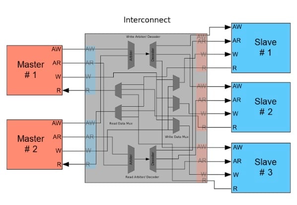
UG761 is the User Guide that contains all the details.
There are three AXI interface protocols:
- AXI4 (supports data bursts)
- AXI4 Lite (single data cycle only)
- AXI4 Stream (referred to as AXIS)
AXI4 and AXI4-Lite are memory mapped protocols.
AXIS uses no address channel, it is a continuous stream of data (eg. pixels)
The AXI protocol uses handshaking, T_READY indicates the slave device is ready to receive.
T_VALID from master to indicate the current data is valid.
T_LAST indicates it is the last data that will be sent.
The AXI Interconnect connects one or more master devices to one or more slave devices.
Want to know more about AXI Interconnect?
Read an explanation by Stephen St. Michael on AllAboutCircuits.
Or have a look at these :
This is just the first of a series of videos by Mohammadsadegh Sadri:
HLS

We have already discussed that in Vivado you can create IP blocks using HDL. Xilinx also focuses on bringing software programmers in the loop.
For this reason they have developed Vivado HLS, this is not the same as Vivado. HLS is High Level Synthesis.
High Level Synthesis gives you the possibility to define your IP blocks in C/C++ language, Vivado HLS will compile this to HDL.
Vivado can then make use of these IP blocks.
An HLS Tutorial can be found here: UG871.
Adam showed us how to compile your own IP block using Vivado HLS and how to add it to the IP repository in Vivado.
Overlays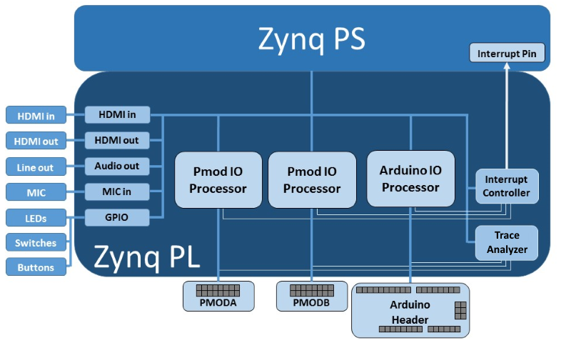
An overlay is a bitstream, so a hardware design that can be loaded to the Programmable Logic using Python.
Adam guided us in creating the bitstream and using that to create an Overlay by writing some python files.
In the end it comes down to copying five files to your PYNQ-Z2 board:
Three files are generated by Vivado (you have to rename them):
- tpd_pynq.hwh (the hardware handoff file and tcl file contain information about the system including clocks, and settings, IP and the system memory map.)
- <project_name>.srcs/sources_1/bd/<project_name>/hw_handoff
- tpd_pynq.tcl
- <project_name>.srcs/sources_1/bd/<project_name>/hw_handoff
- tpd_pynq.bit (this is the bitstream of your overlay)
- ./<vivado project>/<project name>/<design name>.runs/impl_1/
Two files you have to write yourself (see Adam's lab document for the content):
- __init__.py
- tpd_pynq.py
These five files need to be copied to your PYNQ, connect using FileZilla and copy the tpd_pynq folder with those 5 files to the folder:
/home/xilinx/pynq/overlays
Get Running!
Ok, now we know the basics, if you follow Adam's document you should be able to get going.
Now you can connect to http://pynq:9090/lab
And create a new Notebook.
import time
from pynq.overlays.tpg_pynq import tpd_pynqOverlay
import numpy as np
from pynq import pl
from pynq import overlay
from pynq.lib.video import *
from pynq import Xlnk
import cv2
import matplotlib.pyplot as plt

overlay = tpd_pynqOverlay('tpd_pynq.bit')

pixel_in = overlay.pixel_pack_0
pixel_in.bits_per_pixel = 24
colourspace_in = overlay.color_convert_0
rgb2bgr = [0.0, 1.0, 0.0,
 1.0, 0.0, 0.0,
 0.0, 0.0, 1.0,
 0.0, 0.0, 0.0]
colourspace_in.colorspace = rgb2bgr
cam_vdma = overlay.axi_vdma_0
lines = 600
framemode = VideoMode(800, lines, 24)
cam_vdma.readchannel.mode = framemode
cam_vdma.readchannel.start()

tpg = overlay.my_tpg_0

tpg.write(0x10,600)
tpg.write(0x18,800)
tpg.write(0x40,0)
tpg.write(0x30,0)
tpg.write(0x20,0x9)
tpg.write(0x00,0x81)
frame_camera = cam_vdma.readchannel.readframe()
frame_color=cv2.cvtColor(frame_camera,cv2.COLOR_BGR2RGB)
pixels = np.array(frame_color)
plt.imshow(pixels)
plt.show()
When you execute this code, you will get to see a test pattern image.

Fun part
Create your own Test Pattern Generator
I followed the first webinar using Windows 10. I will be doing this in Ubuntu Focal Fossa (20.04, kernel 5.6.14), which should work all the same.
Adam showed us how to setup our system to create an overlay for the PYNQ-Z2.
During the webinar we used a Test Pattern Generator created by Xilinx, you can find more information about that in this document.
You'll find some interesting parameters in there to change the output of the pattern generator.
But... the source of this IP block is not available  .
.
So I decided I was going to build my own Test Pattern Generator. Let's get started.
Before running HLS do:
sudo apt-get install libjpeg62
sudo add-apt-repository ppa:linuxuprising/libpng12
sudo apt update
sudo apt install libpng12-0source /tools/Xilinx/Vivado/2019.1/settings64.sh
export LIBRARY_PATH=/usr/lib/x86_64-linux-gnu:$LIBRARY_PATH
/tools/Xilinx/Vivado/2019.1/vivado_hls
This is an interesting starting point which I used:
It is in fact part a whole series of interesting tutorials:
Some extra info about Processor control of HLS Designs.
After following that tutorial 14 I created a new bitstream and had a red image in my Jupyter notebook. This is the code of my HLS IP block:
#include "math.h"
#include <hls_video.h>

#define HEIGHT 600
#define WIDTH  800

typedef hls::stream<ap_axiu<24,1,1,1> > AXI_STREAM;

void my_tpg(AXI_STREAM& m_axis_video);
ap_uint<24> set_rgb_8_pixel_value(hls::rgb_8 pixel);

//Top Level Function
void my_tpg(AXI_STREAM& m_axis_video)
{
#pragma HLS INTERFACE s_axilite register port=return
#pragma HLS INTERFACE axis register both port=m_axis_video
ap_axiu<24, 1, 1, 1> video;
hls::rgb_8 pixel;

//Add code for output video generation here

for(int i = 0; i < HEIGHT; i++)
{
#pragma HLS UNROLL factor=2
         for(int j= 0; j < WIDTH; j++)
         {
             pixel.R =255;//(int)N*16;
             pixel.B =0;//(int)N*16;
             pixel.G =0;//(int)N*16;

        // Start of frame, assert tuser
             if((i==0)&&(j==0))
                    video.user=1;
             else
                    video.user=0;

             //End of line, assert tlast
             if(j==WIDTH-1)
                    video.last = 1;
             else
                    video.last = 0;

             // Assign the pixel value to the data output
             video.data = set_rgb_8_pixel_value(pixel);

             //Send video to stream
             m_axis_video << video;
         }
     }

     //Delay until it's time for the next frame
     for (int c=0;c<125000000/60;)
          c++;

}

ap_uint<24> set_rgb_8_pixel_value(hls::rgb_8 pixel)
{
     ap_uint<24> pixel_out;
     pixel_out = (pixel.R << 16) + (pixel.B << 8) + pixel.G;
     return pixel_out;

}

Ok, we see a red screen, great!
Get it out over HDMI Output
Let's get it on HDMI output as well.
This is helpful for PYNQ-Z2
Use an AXI Broadcast IP to split the video stream.
Connect everything up. Have a look at the pdf in attachment for a high resolution image of the block design.
Generate the bitstream. Copy it to the PYNQ-Z2. These steps are the same as described in Adam's lab document.
Create a new python notebook
import time
from pynq.overlays.tpd_pynq import tpd_pynqOverlay
import numpy as np
from pynq import pl
from pynq import overlay
from pynq.lib.video import *
from pynq import Xlnk
import cv2
import matplotlib.pyplot as plt
overlay = tpd_pynqOverlay('tpd_pynq.bit')

tpg = overlay.my_tpg_0
vtc = overlay.v_tc_0
tpg.write(0x10,600)
tpg.write(0x18,800)
vtc.write(0x00,0x01)
Connect a screen to HDMI out.
Tip
When HDMI output is connected to your screen, the PYNQ gets power via HDMI. turning it off and on again with the power switch will not work. Unplug HDMI as well.

Green (I updated the HLS code) screen? Yeah! Done. Boring...
Of course you can animate that...
Animate a block so it bounces up and down:
#include "math.h"
#include <hls_video.h>
#define HEIGHT 600
#define WIDTH  800
typedef hls::stream<ap_axiu<24,1,1,1> > AXI_STREAM;
void my_tpg(AXI_STREAM& m_axis_video);
ap_uint<24> set_rgb_8_pixel_value(hls::rgb_8 pixel);

float t=75;
int BOXSIZE = 50;
int ypos=2*BOXSIZE;
int xpos=200;
int dir=-1;
int framecount=0;
//Top Level Function
void my_tpg(AXI_STREAM& m_axis_video)
{
#pragma HLS INTERFACE s_axilite register port=return
#pragma HLS INTERFACE axis register both port=m_axis_video
ap_axiu<24, 1, 1, 1> video;
hls::rgb_8 pixel;
     t=75;
     while (framecount++<6000){
     //Add code for output video generation here
     if ((ypos>=HEIGHT-2*BOXSIZE)||(ypos<=2*BOXSIZE)) {
          dir=-dir;
     }
     ypos+=dir;
     for(int i = 0; i < HEIGHT; i++)
     {
#pragma HLS UNROLL factor=2
     t = t - 0.1;
     if (t--==0)t=75;
         for(int j= 0; j < WIDTH; j++)
         {
        if (    (j>xpos-BOXSIZE && j<xpos+BOXSIZE)
        && (i>ypos-BOXSIZE && i<ypos+BOXSIZE)){
             pixel.R =0;
             pixel.B =255;
             pixel.G =0;
             }
             else{
             pixel.R =255;
             pixel.B =0;
             pixel.G =0;
             }
        // Start of frame, assert tuser
             if((i==0)&&(j==0))
                    video.user=1;
             else
                    video.user=0;
             //End of line, assert tlast
             if(j==WIDTH-1)
                    video.last = 1;
             else
                    video.last = 0;
             // Assign the pixel value to the data output
             video.data = set_rgb_8_pixel_value(pixel);
             //Send video to stream
             m_axis_video << video;
         }
     }
     //Delay until it's time for the next frame
     for (int c=0;c<125000000/60;)
          c++;
     }
}
ap_uint<24> set_rgb_8_pixel_value(hls::rgb_8 pixel)
{
     ap_uint<24> pixel_out;
     pixel_out = (pixel.R << 16) + (pixel.B << 8) + pixel.G;
     return pixel_out;
}
Yeah! Done. Boring...
Tea Storm, I can do that... sort of...
Afterthought
Ok, I admit, I was going too fast here... My goal was to get the Tea Storm demo running on the PYNQ-Z2. I started implementing the code without understanding the algorithm or thinking about hardware too much. It is important to know more about how the fpga is going to implement this in hardware and how this can be optimized. I just didn't have enough time this week to get more in-depth in this.
I do think it should be possible to accelerate this a lot since you can do the calculations in parallel.
I really would appreciate the insight of someone how knows more about this and can give me some tips on how to tackle and optimize this.
The algorithm uses raymarching. For every pixel you calculate the distance to your object in increments until you are inside the object. This defines the color of the pixel. The further the pixel is, the darker the color.
In the end it works, but very slow...

I know, it doesn't look the same as in the video on the top of the page:
- It is a still image, if you calculate for different values of t it does move as the Tea Storm demo.
- I calculate 16x as much data as in the original Tea Storm of p01. Drawing squares with this algorithm seems more difficult since you do calculations per pixel.
- p01 calculates it 75x75 times and uses N to change the size of the square, p01 draws a square of size 0<N<4 at location (x*4,y*4) which creates an optical illusion that the color is a gradient.
- I calculate N for every pixel and change the color to N*16 (hoping that x16 is done fast with a bit shift).
#include "math.h"
#include <hls_video.h>

#define HEIGHT 600
#define WIDTH  800

typedef hls::stream<ap_axiu<24,1,1,1> > AXI_STREAM;

void my_tpg(AXI_STREAM& m_axis_video);
ap_uint<24> set_rgb_8_pixel_value(hls::rgb_8 pixel);

float twirlingsphere(float X, float Y, float Z, float t, float D){
     return (X*X+Y*Y*cosf(t/6+cosf(D-X-Y))+Z*Z)/9-1+cosf(X+t)*cosf(Y-t);
}

float calcDist(int i, int j, float X, float Y, float Z, float D, float Ddiv2, float N, float d, float t){
     while(.1<d*N){
#pragma HLS INLINE
            X=D*j/HEIGHT-Ddiv2;
            Y=D*i/HEIGHT-Ddiv2;
            Z=Ddiv2-9;
            N-=.1;
            d = twirlingsphere(X,Y,Z,t,D);
            D+=d;
            Ddiv2 = D/2;
     }
     return N;
}

float t=75;
int BOXSIZE = 50;
int ypos=2*BOXSIZE;
int xpos=200;
int dir=-1;
int framecount=0;

//Top Level Function
void my_tpg(AXI_STREAM& m_axis_video)
{
#pragma HLS INTERFACE s_axilite register port=return
#pragma HLS INTERFACE axis register both port=m_axis_video
ap_axiu<24, 1, 1, 1> video;
hls::rgb_8 pixel;

     t=75; // Everyone needs some T, right?

     while (framecount++<6000){
     //Add code for output video generation here
     if ((ypos>=HEIGHT-2*BOXSIZE)||(ypos<=2*BOXSIZE)) {
          dir=-dir;
     }
     ypos+=dir;

     for(int i = 0; i < HEIGHT; i++)
     {
#pragma HLS UNROLL factor=2
     t = t - 0.1;
     if (t--==0)t=75;
     for(int j= 0; j < WIDTH; j++)
         {
           float D = 4.0;
           float Ddiv2 = 2.0;
           float X=4.0*j/HEIGHT-2.0;
           float Y=4.0*i/HEIGHT-2.0;
           float Z=-7.0;
           float N=4.0;
           float d = twirlingsphere(X,Y,Z,t,D);
           N = calcDist(i,j,X,Y,Z,D,Ddiv2,N,d,t);


        if (    (j>xpos-BOXSIZE && j<xpos+BOXSIZE)
        && (i>ypos-BOXSIZE && i<ypos+BOXSIZE)){
             pixel.R =0;//(int)N*16;
             pixel.B =255;//(int)N*16;
             pixel.G =0;//(int)N*16;
             }
             else{
             pixel.R =255;//(int)N*16;
             pixel.B =0;//(int)N*16;
             pixel.G =0;//(int)N*16;
             }

        // Start of frame, assert tuser
             if((i==0)&&(j==0))
                    video.user=1;
             else
                    video.user=0;

             //End of line, assert tlast
             if(j==WIDTH-1)
                    video.last = 1;
             else
                    video.last = 0;

             // Assign the pixel value to the data output
             video.data = set_rgb_8_pixel_value(pixel);

             //Send video to stream
             m_axis_video << video;
         }
     }

     //Delay until it's time for the next frame
     for (int c=0;c<125000000/60;)
          c++;
     }
}

ap_uint<24> set_rgb_8_pixel_value(hls::rgb_8 pixel)
{
     ap_uint<24> pixel_out;
     pixel_out = (pixel.R << 16) + (pixel.B << 8) + pixel.G;
     return pixel_out;
}
Tip
Board presets for the PYNQ-Z2
In Vivado you have to connect the outputs of your design to hardware pins. This can be a hassle. Board presets help to do this easier.
A board preset file is an xdc file. Which is a constraints file with all the pins of your board added as comments.
You just have to uncomment the lines for the pins you need and change the name of the pins.
You can download the XDC constraints for the PYNQ-Z2 file at the bottom of this site.
| my_tpg.pdf |

Top Comments