


A little step by step SMD soldering 
http://goodfet.sourceforge.net/
http://goodfet.sourceforge.net/hardware/facedancer11/
The purpose of this board is to allow USB devices to be written in host-side Python, so that one workstation can fuzz-test the USB device drivers of another host. There are also a ton of other cool things you can do with your own Python scripts.
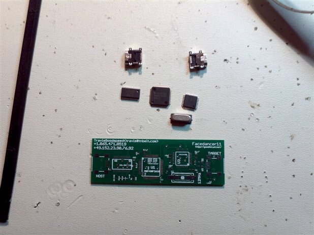
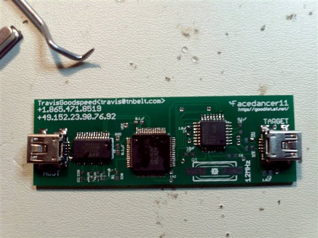
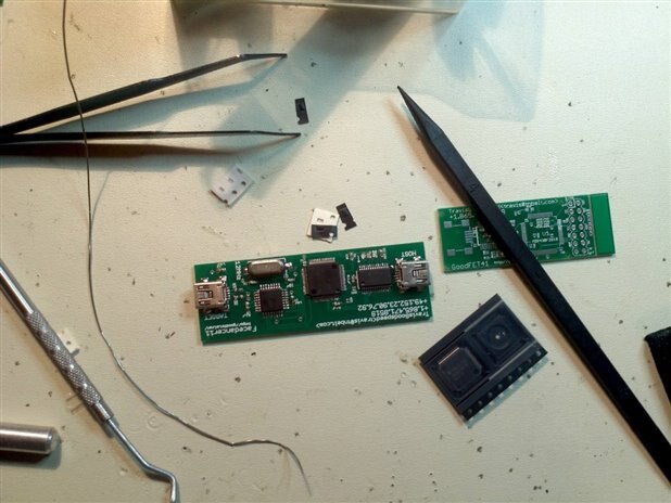
First I picked all the big components, 2 Mini USB females, 1 FT232RL(SSOP28), 1 MSP430F2618TPM(QFP64). MAX3420E(LQFP32) and 12MHz SMD Crystal.
Next I added a bit of flux to the board to help stop bridging.
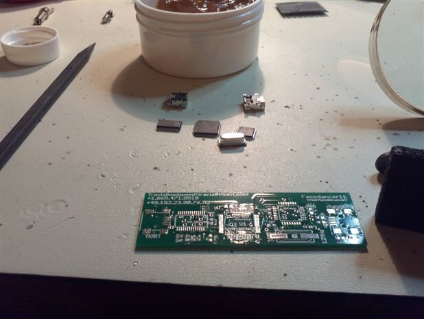
The first componets I soldered are the Mini USBs starting with the outside tabs then the data connetions.

Next on the list is the MSP430 using a one sided chiseled tip and the drag method, be careful not too use to much solder I hold the chip down with a non-conductive plastic wires twisters to center and tack one side.
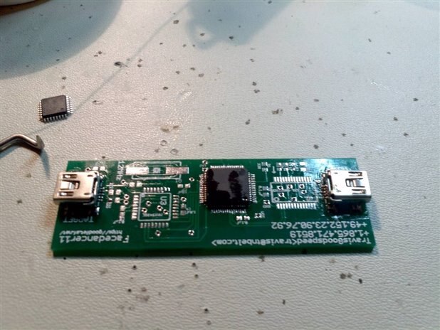
Now for the FTDI using the same method but lesser pins makes it much easier
Now for the Max same method but even easier then the last two ICs
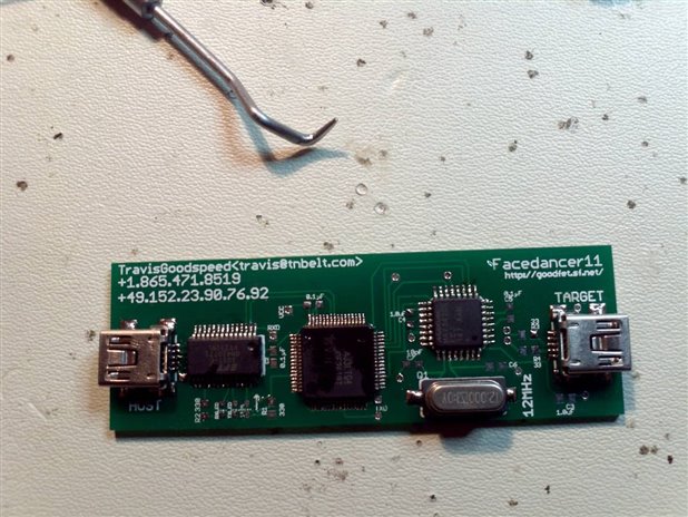
Next the 12Mhz crystal
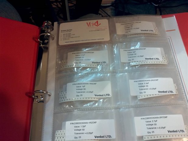
now use a magnifying glass to make sure there are no bridges. It's time for the 0630 parts 2 1.0uF Capacitors, 3 0.1uF Decoupling Capacitors. 2 18pF Capacitors 2 330ohm LED resistors and 3 LEDS
I used non conductive tweezers and just a tack of solder for the caps and LEDs
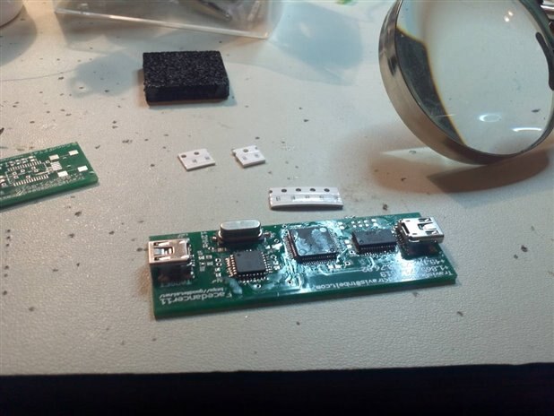
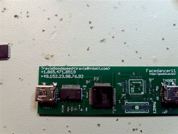
Once everyhing is soldered on give it a look under a magnifying glass
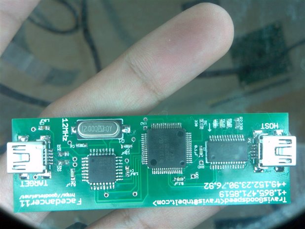
If everything looks good, connect it and the LEDs should blink, then go to the site above to load the firmware and have some fun.
I hope you enjoyed my post. when the headers I ordered come in I'll post a video of soldering them on the Freescale FRM-KL25Z Freedom.
Thanks for reading
F/S
Top Comments