element14 Community
element14 Community
    Register Log In
  • Site
  • Search
  • Log In Register
  • Community Hub
    Community Hub
    • What's New on element14
    • Feedback and Support
    • Benefits of Membership
    • Personal Blogs
    • Members Area
    • Achievement Levels
  • Learn
    Learn
    • Ask an Expert
    • eBooks
    • element14 presents
    • Learning Center
    • Tech Spotlight
    • STEM Academy
    • Webinars, Training and Events
    • Learning Groups
  • Technologies
    Technologies
    • 3D Printing
    • FPGA
    • Industrial Automation
    • Internet of Things
    • Power & Energy
    • Sensors
    • Technology Groups
  • Challenges & Projects
    Challenges & Projects
    • Design Challenges
    • element14 presents Projects
    • Project14
    • Arduino Projects
    • Raspberry Pi Projects
    • Project Groups
  • Products
    Products
    • Arduino
    • Avnet & Tria Boards Community
    • Dev Tools
    • Manufacturers
    • Multicomp Pro
    • Product Groups
    • Raspberry Pi
    • RoadTests & Reviews
  • About Us
  • Store
    Store
    • Visit Your Store
    • Choose another store...
      • Europe
      •  Austria (German)
      •  Belgium (Dutch, French)
      •  Bulgaria (Bulgarian)
      •  Czech Republic (Czech)
      •  Denmark (Danish)
      •  Estonia (Estonian)
      •  Finland (Finnish)
      •  France (French)
      •  Germany (German)
      •  Hungary (Hungarian)
      •  Ireland
      •  Israel
      •  Italy (Italian)
      •  Latvia (Latvian)
      •  
      •  Lithuania (Lithuanian)
      •  Netherlands (Dutch)
      •  Norway (Norwegian)
      •  Poland (Polish)
      •  Portugal (Portuguese)
      •  Romania (Romanian)
      •  Russia (Russian)
      •  Slovakia (Slovak)
      •  Slovenia (Slovenian)
      •  Spain (Spanish)
      •  Sweden (Swedish)
      •  Switzerland(German, French)
      •  Turkey (Turkish)
      •  United Kingdom
      • Asia Pacific
      •  Australia
      •  China
      •  Hong Kong
      •  India
      •  Korea (Korean)
      •  Malaysia
      •  New Zealand
      •  Philippines
      •  Singapore
      •  Taiwan
      •  Thailand (Thai)
      • Americas
      •  Brazil (Portuguese)
      •  Canada
      •  Mexico (Spanish)
      •  United States
      Can't find the country/region you're looking for? Visit our export site or find a local distributor.
  • Translate
  • Profile
  • Settings
Personal Blogs
  • Community Hub
  • More
Personal Blogs
Legacy Personal Blogs This triggers That ... PCB No.2
  • Blog
  • Documents
  • Mentions
  • Sub-Groups
  • Tags
  • More
  • Cancel
  • New
  • Share
  • More
  • Cancel
Group Actions
  • Group RSS
  • More
  • Cancel
Engagement
  • Author Author: drlucyrogers
  • Date Created: 10 Jul 2015 3:16 PM Date Created
  • Views 2205 views
  • Likes 2 likes
  • Comments 7 comments
  • thingatron
  • eagle
  • eagle-cad
  • raspberry_pi
  • optoisolator
  • dr_lucy_rogers
  • @drlucyrogers
  • lucy_rogers
Related
Recommended

This triggers That ... PCB No.2

drlucyrogers
drlucyrogers
10 Jul 2015

image


Thingatrons (blog post here) - the open collector driver boards that I (Lucy Rogers) made to control outputs from the GPIO pins on a Raspberry Pi - were great, but I realised I also needed to use various inputs to trigger the outputs.


And because I want my *things* to work out in the real world, and not just on my workbench, I use inputs that trigger on 12V, such as a motion detector or PIR.


If there's any kind of fault on the wiring or in the input, I could easily fry the Pi. Therefore I wanted to electrically isolate my inputs from the Pi. Fortunately there's a cunning way of doing this, using something called an optoisolator (also known as optocoupler or photo-coupler) . These are component that use a light emitting diode to trigger a light sensitive transistor. There's a nice article on optoisolators here.


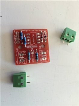
Although I could make a one-off using some veroboard, I knew one would never be enough ... so I made a couple of PCB's ...


I again used Cadsoft's Eagle PCB Design Software - and again I was very grateful to the help given by James Macfarlane, who uses the software regularly.


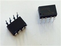
Finding which parts to use and their corresponding items in the Eagle libraries was still the most difficult part. I used a dual-channel optoisolator (photo below), which means there are two LED's and two transistors inside the one component - therefore I could run two inputs through one PCB.


image


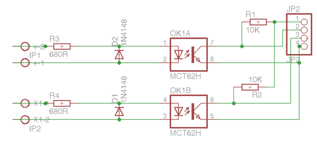
Here's the schematic:


image

Here's what I used, which Eagle library they were in and what they were called and their Farnell Part Number:


My DescriptionEagle LibraryDevicePackageValue (User input)Farnell Part NumberFarnell Link
Header: 4 pins x 1 rowpinheadPINHD-1X41X042356153http://grh.premierfarnell.com/pageredir.aspx?c=EU1&u=jsp/search/productListing.jsp?CMP=SOM-e14-Blog-LRo-Cadsoft-OpenCollector%26SKUS=2356153
Resistor: 680 ohmrclR-EU_0207/10 (R-EU_)0207/10680R9342168
http://grh.premierfarnell.com/pageredir.aspx?c=EU1&u=jsp/search/productListing.jsp?CMP=SOM-e14-Blog-LRo-Firecrackers%26SKUS=9342168
Resistor: 10K ohmrclR-EU_0207/10 (R-EU_)0207/1010K9341110
http://grh.premierfarnell.com/pageredir.aspx?c=EU1&u=jsp/search/productListing.jsp?CMP=SOM-e14-Blog-LRo-Firecrackers%26SKUS=9341110
OptoIsolatoroptocouplerILD2DIL081612474
http://grh.premierfarnell.com/pageredir.aspx?c=EU1&u=jsp/search/productListing.jsp?CMP=SOM-e14-Blog-LRo-Firecrackers%26SKUS=1612474
Terminal Block: AK500/2con-ptr500AK500/2AK500/2PWR1641947http://grh.premierfarnell.com/pageredir.aspx?c=EU1&u=jsp/search/productListing.jsp?CMP=SOM-e14-Blog-LRo-Cadsoft-OpenCollector%26SKUS=1641947
Diode: 1N4148diode1N4148DO35-7 (1N4148)DO35-71N41481081177http://grh.premierfarnell.com/pageredir.aspx?c=EU1&u=jsp/search/productListing.jsp?CMP=SOM-e14-Blog-LRo-Cadsoft-TrafficLight%26SKUS=1081177


Once the schematic was drawn, I could move on to board. I spent ages re-arranging everything so I could use the smallest board possible (the PCB manufacturers charge by the size of board).


I was advised to route the board by hand since the autorouter is overkill for such a simple board. Also, the autorourter needs quite a lot of set-up in order for it not to do strange things.


Some other hints and tips included:

  • If you want to re-route a track you can use the "Rip-Up" icon. Double clicking a track rips-up the whole signal and returns it to the airwires, or yellow straight lines.
  • Use the "ERC" button to check the electrical connections
  • Use the "DRC" button to check if the design fits. This shows things like if the track is too close to the edge of the board.
  • Some tracks can be made thicker, particularly if they have a larger load on them. This can be done a few ways, but I find changing the "width" in "Properties" the simplest. (Use the "i" for info icon).
  • By "smashing" a component, you can separate the name or value from a part. This lets you move the name to a more convenient position.
  • Add mounting holes to the board, so you can secure it later.


Here's the finished board in Eagle:

image

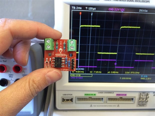
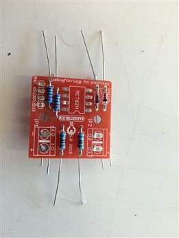
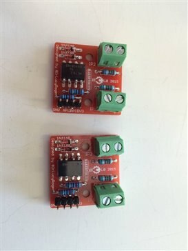
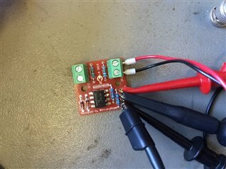
I then made the gerber files (search online for how to do this) and sent them off to Ragworm. I may have got a little bit over-excited when the boards arrived. I then added the components and ran some tests:


imageimageimage


imageimageimage


Once I was happy that everything worked, I used it in my first application - the Firecrackers - blog post and video here.


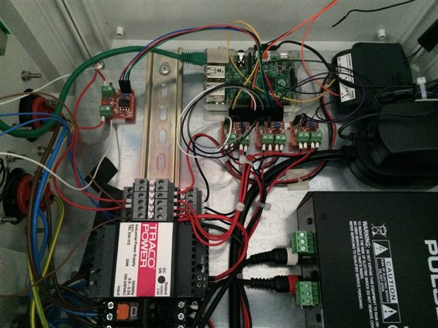
The photo below shows the optoisolator in the top left corner of the Firecrackers control box (the three other orange PCB's are the Thingatrons).


image


UPDATE 6th August 2015


The optoisolator Gerber files are available to buy here.


*Note this PCB is designed to protect the Pi from damage due to Earth Loops - it is not designed to withstand to mains voltage levels between input and output.*

  • Sign in to reply

Top Comments

  • DAB
    DAB over 10 years ago +1
    Very nice design. I agree, setting up isolation between unknown sources and your device is a very smart idea and you have developed a very nice solution. Well done. DAB
  • derkarhu
    derkarhu over 10 years ago +1
    If you 'split' the input resistor into two components, and added a Zener diode between the mid-point of the resistors and the LED cathode, you would have an extended input voltage range, with a guaranteed…
  • phil.s
    phil.s over 10 years ago +1
    No pleasing some folk - beware the Arduino Forum. For first tries, not bad and I do know just how much work goes in, as well as a lot to learn. Electrons don't much care about angles, but you have plenty…
Parents
  • Former Member
    Former Member over 10 years ago

    In my opinion, PCB design is not good. I use Eagle for many years. It is great tool, but in beginning I had troubles with using it, because it has a little strange control for beginners. To be concrete, I didn't like these things on your design:

    1. Wires are too thin. If you can, use wider wires for bigger current. For your design you can use 32mils.

    2. Wire angles are not 45 and 90 degrees. it is a good practice to have wires with these angles. It looks better. You can check this option in DRC check.

    3. Some wires are too close. Yo can enable grid. I usually use 50 mils grid for simple PCBs like yours or 25 mils grid for complex SMD boards.

    4. Primary and secondary part are too close. It is a good idea to have bigger space between them to better isolation specially when some overvoltage peak goes there.

    5. Your design is double-sided which is needless. With some little changes like rotation of R4 and more space between wires around optocoupler you can have single-sided design, which can be reproduced also in amateur conditions, not only at professional PCB manufacturer.

    • Cancel
    • Vote Up 0 Vote Down
    • Sign in to reply
    • More
    • Cancel
  • drlucyrogers
    drlucyrogers over 10 years ago in reply to Former Member

    Thank you for your comment. I have incorporated some of your points in the next version.

    • Cancel
    • Vote Up 0 Vote Down
    • Sign in to reply
    • More
    • Cancel
Comment
  • drlucyrogers
    drlucyrogers over 10 years ago in reply to Former Member

    Thank you for your comment. I have incorporated some of your points in the next version.

    • Cancel
    • Vote Up 0 Vote Down
    • Sign in to reply
    • More
    • Cancel
Children
No Data
element14 Community

element14 is the first online community specifically for engineers. Connect with your peers and get expert answers to your questions.

  • Members
  • Learn
  • Technologies
  • Challenges & Projects
  • Products
  • Store
  • About Us
  • Feedback & Support
  • FAQs
  • Terms of Use
  • Privacy Policy
  • Legal and Copyright Notices
  • Sitemap
  • Cookies

An Avnet Company © 2025 Premier Farnell Limited. All Rights Reserved.

Premier Farnell Ltd, registered in England and Wales (no 00876412), registered office: Farnell House, Forge Lane, Leeds LS12 2NE.

ICP 备案号 10220084.

Follow element14

  • X
  • Facebook
  • linkedin
  • YouTube