element14 Community
element14 Community
    Register Log In
  • Site
  • Search
  • Log In Register
  • Community Hub
    Community Hub
    • What's New on element14
    • Feedback and Support
    • Benefits of Membership
    • Personal Blogs
    • Members Area
    • Achievement Levels
  • Learn
    Learn
    • Ask an Expert
    • eBooks
    • element14 presents
    • Learning Center
    • Tech Spotlight
    • STEM Academy
    • Webinars, Training and Events
    • Learning Groups
  • Technologies
    Technologies
    • 3D Printing
    • FPGA
    • Industrial Automation
    • Internet of Things
    • Power & Energy
    • Sensors
    • Technology Groups
  • Challenges & Projects
    Challenges & Projects
    • Design Challenges
    • element14 presents Projects
    • Project14
    • Arduino Projects
    • Raspberry Pi Projects
    • Project Groups
  • Products
    Products
    • Arduino
    • Avnet Boards Community
    • Dev Tools
    • Manufacturers
    • Multicomp Pro
    • Product Groups
    • Raspberry Pi
    • RoadTests & Reviews
  • Store
    Store
    • Visit Your Store
    • Choose another store...
      • Europe
      •  Austria (German)
      •  Belgium (Dutch, French)
      •  Bulgaria (Bulgarian)
      •  Czech Republic (Czech)
      •  Denmark (Danish)
      •  Estonia (Estonian)
      •  Finland (Finnish)
      •  France (French)
      •  Germany (German)
      •  Hungary (Hungarian)
      •  Ireland
      •  Israel
      •  Italy (Italian)
      •  Latvia (Latvian)
      •  
      •  Lithuania (Lithuanian)
      •  Netherlands (Dutch)
      •  Norway (Norwegian)
      •  Poland (Polish)
      •  Portugal (Portuguese)
      •  Romania (Romanian)
      •  Russia (Russian)
      •  Slovakia (Slovak)
      •  Slovenia (Slovenian)
      •  Spain (Spanish)
      •  Sweden (Swedish)
      •  Switzerland(German, French)
      •  Turkey (Turkish)
      •  United Kingdom
      • Asia Pacific
      •  Australia
      •  China
      •  Hong Kong
      •  India
      •  Korea (Korean)
      •  Malaysia
      •  New Zealand
      •  Philippines
      •  Singapore
      •  Taiwan
      •  Thailand (Thai)
      • Americas
      •  Brazil (Portuguese)
      •  Canada
      •  Mexico (Spanish)
      •  United States
      Can't find the country/region you're looking for? Visit our export site or find a local distributor.
  • Translate
  • Profile
  • Settings
Personal Blogs
  • Community Hub
  • More
Personal Blogs
Legacy Personal Blogs TI Hercules RM46 Three-Phase Generator With Transformers Part 1
  • Blog
  • Documents
  • Mentions
  • Sub-Groups
  • Tags
  • More
  • Cancel
  • New
  • Share
  • More
  • Cancel
Group Actions
  • Group RSS
  • More
  • Cancel
Engagement
  • Author Author: martinvalencia
  • Date Created: 11 Jun 2017 11:23 PM Date Created
  • Views 2433 views
  • Likes 6 likes
  • Comments 10 comments
  • h bridge
  • rm46
  • threehase
  • pwm
  • inverter
  • texas instruments
  • etpwm
Related
Recommended

TI Hercules RM46 Three-Phase Generator With Transformers Part 1

martinvalencia
martinvalencia
11 Jun 2017
INTRODUCTION

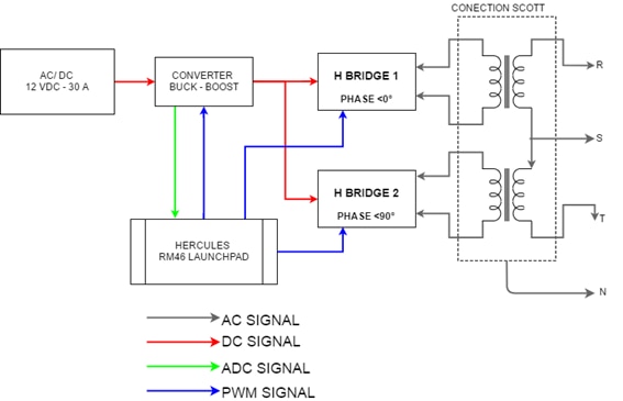
My goal is to design a device that generates a three-phase signal starting from a voltage in DC.

I have a 12VDC power supply and through H bridges, power supply of the transformers in the SCOTT configuration, both transformers with their special connection send me the signals R, S, T plus a Neutral.

Between my airplanes is to vary the voltage of the power supply with a reducing reducer converter.

The system will be controlled by a microcontroller Hercules RM46, this internal has an ETPWM module, which allows me to generate PWM signals with special characteristics, such as bandwidth, phase angle, synchronization in PWM, among others.

Attached

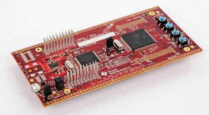
Part 2:

TI Hercules RM46 Three-Phase Generator With IGCM15F60GA Part 2

Microcontroller:

LAUNCHXL2-RM46 Hercules RM46x LaunchPad Development Kit | TI.com

User Guide  

Technical Reference Manual

Facebook:

Electronaplica

BLOCKS DIAGRAM

image

*The image of the transformer is referential


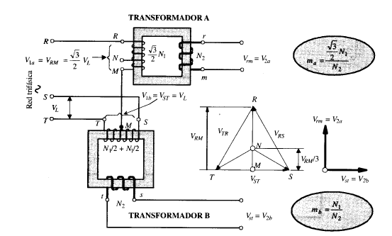
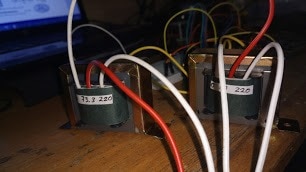
CIRCUIT ELECTRICAL BACKGROUND - SCOTT CONNECTION

This is a contribution of Frank Rodrigo Coaquira Molleapaza (Electrical Engineer).

It is a connection of two single-phase transformer to convert a system of three-phase voltages in biphasic and vice versa.


This arrangement is due to the American engineer Charles F. Scott, who invented it in 1984 while working at the company Westinghouse and is based on the well-known fact that the three-phase star system composed voltage between two phases is in square with the voltage Simple third phase.


image

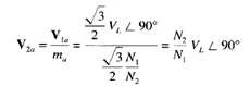
Equation for output V2a:

image

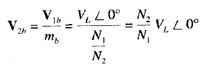
Equation for output V2b:

image

Fragment of text, extracted from the book:


Pag 243. “Maquinas Electricas – Jesus Fraile Mora”


Conclusion: from the previous fragment, it tells us that you must have two alternating signals of the same frequency with a phase shift of 90 degrees between them.


About the Microcontroller

The HerculesTm RM46x LaunchPadTm Development Kit is an inexpensive evaluation platform designed to help you get started quickly in evaluating and developing with the Hercules microcontroller platform. The LaunchPad Development Kit is based on the IEC 61508 SIL 3 certified RM46L852, which is a lockstep ARMRegistered CortexRegistered-R4F based MCU with integrated safety features and peripherals such as two 12-bit ADCs, programmable High-End timers, motor control peripherals (eQEP, eCAP, ePWM), USB, Ethernet, MibSPI and serial communication interfaces. Hercules RM MCUs can help reduce the development effort of IEC 61508 functional safety applications.


image


ETPWM Enhanced Pulse Width

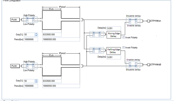
The enhanced pulse width modulator (ePWM) peripheral is a key element in Modulator controlling many of the power electronic systems found in both commercial and industrial equipments. These systems include digital motor control, switch mode power supply control, uninterruptible power supplies (UPS), and other forms of power conversion. The ePWM peripheral performs a digital to analog (DAC) function, where the duty cycle is equivalent to a DAC analog value; it is sometimes referred to as a Power DAC.


As we can see in the image, you can see that ETPWM module uses two output pins of the microcontroller, side A and B, both outputs can be with the same polarity or one in reverse of the other.


The resolution of the module is of nanoseconds, generating a high resolution in the dutty cycle and in the dead band.


image


Code Example CCSV7


int main(void)

{

/* USER CODE BEGIN (3) */

  etpwmDeadBandConfig_t pwm_deadband_config; // declaracion de variable

  etpwmInit();


  /*Configuracion del angulo de desfase entre los PWM generados*/

  etpwmSetSyncOut(etpwmREG1, SyncOut_CtrEqZero);

  etpwmSetSyncOut(etpwmREG2, SyncOut_EPWMxSYNCI); //SyncOut_CtrEqZero);


  etpwmDisableCounterLoadOnSync(etpwmREG1);

  etpwmEnableCounterLoadOnSync(etpwmREG2, 8300, COUNT_DOWN); // seting del angulo de


  /*Configuracion de la banda muerta*/

  pwm_deadband_config.halfCycleEnable = false;

  pwm_deadband_config.inputmode = PWMA_RED_PWMB_FED;

  pwm_deadband_config.outputmode = PWMB_FED_PWMA_RED;

  pwm_deadband_config.polarity = Invert_PWMB;

  /*Iniciando la carga de los valor de la banda muerta 1000---> 510 microsegundos*/

  etpwmSetDeadBandDelay(etpwmREG1, 1000, 1000);

  etpwmEnableDeadBand(etpwmREG1, pwm_deadband_config);

  etpwmSetDeadBandDelay(etpwmREG2, 1000, 1000);

  etpwmEnableDeadBand(etpwmREG2, pwm_deadband_config);


  while (1)

  ;

  /* USER CODE END */


    return 0;

}


Pin Conection

File:LAUNCHXL2 TMS57012 RM46 REVA.pdf - Texas Instruments Wiki
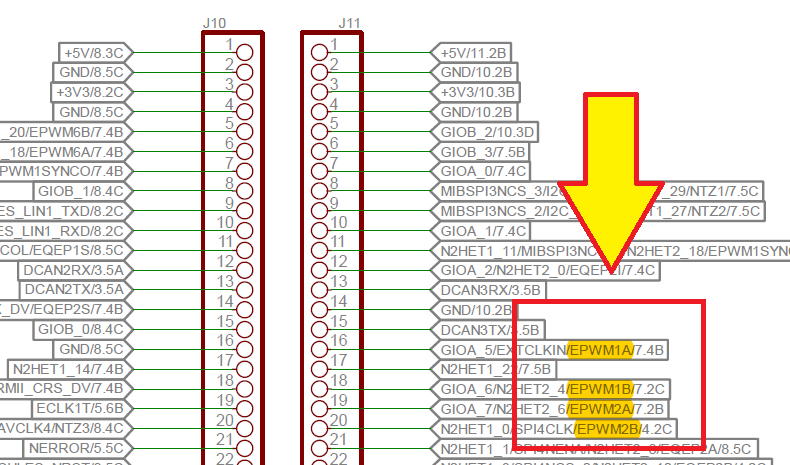
image


Schematic

image

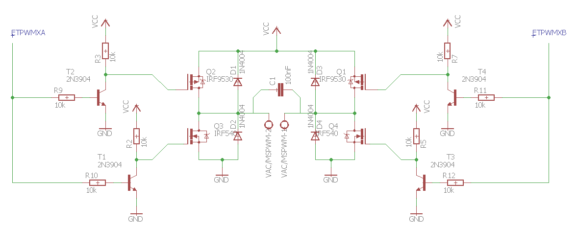
In the schematic there is a simple inverter bridge excited by transistors and using MOSFET to perform the energy switching

Two of these bridges are used for the project.


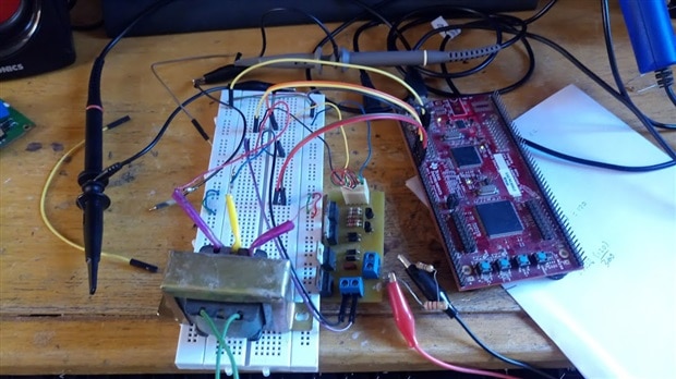
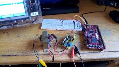
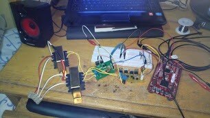
IMPLEMENTATION PHOTOS

In the following images you can see the implementation using only one transformer.

image

image

image

image

  Output voltage waveform
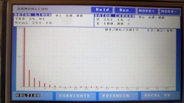
image

  Voltage spectrum

image


Operation Videos - Spanish

First part of the operation

You don't have permission to edit metadata of this video.
Edit media
x
image
Upload Preview
image

Second part of the operation

You don't have permission to edit metadata of this video.
Edit media
x
image
Upload Preview
image

  • Sign in to reply

Top Comments

  • Jan Cumps
    Jan Cumps over 8 years ago in reply to balearicdynamics +2
    It's going to work, Enrico. Martin and I have done several projects together - if you're interested in automotive, industrial or medical safety (I know you are ) , you can always join us for a next project…
  • Jan Cumps
    Jan Cumps over 8 years ago in reply to jc2048 +2
    That could likely be solved by configuring the deadband in the PWM module. I've done that for half-bridge, not for 3-phase though. There's a HET example that generates 3 phase signals from the timer module…
  • balearicdynamics
    balearicdynamics over 8 years ago +1
    Sounds a good project with solid bases. Despite the correctness I can't evaluate I appreciate your details in this project premises and the theory explained. I will follow this work, it sounds I can learn…
  • martinvalencia
    martinvalencia over 8 years ago in reply to Jan Cumps

    It is true that etpwm, is very powerful Hercules has enough modules to control a three-phase bridge, the example code I put above could help to control the triphasic.

    Once I get some GaN samples for high power, I will try to produce the three-phase signal in this way.

    Saludos amigo!

    • Cancel
    • Vote Up 0 Vote Down
    • Sign in to reply
    • More
    • Cancel
  • martinvalencia
    martinvalencia over 8 years ago in reply to jc2048

    No, I'm sure of why the graphics come out that way, maybe they'll work out fine if you consider adding a 10k resistor at the half bridge output.

    In reality this works that way with a resistor, I am not working with high currents at the maximum one ampere, so I consider a current in milliamps to exite the internal capacitor of the mosfets, in the datasheet there is a graph of Charge vs excitation voltage, from there my calculations for the exit current of the damper.


    image


    In this graph selecting a 12 volt work and gives me a load of 55nC.

    • Cancel
    • Vote Up 0 Vote Down
    • Sign in to reply
    • More
    • Cancel
  • martinvalencia
    martinvalencia over 8 years ago in reply to balearicdynamics

    Hi Enrico, I'm glad you like my work, as presented here is just the initial part in which using a single inverter bridge and a single transformer.

    I'm still working on the implementation of the SCOOT configuration of the transformers, this progress will be presented in the next blog.

    I hope we can work together on some project, with Jan I have done several jobs and it is always nice to have someone else.


    regards

    Martin

    • Cancel
    • Vote Up 0 Vote Down
    • Sign in to reply
    • More
    • Cancel
  • Jan Cumps
    Jan Cumps over 8 years ago in reply to jc2048

    Jon Clift wrote:


    Does this Hercules board have enough PWMs for deadband control?


    It can be independently (or dependently) set for each of the 6 or 7 complementary PWM modules,


    image

    Here's a signal that I created with one of these PWM pairs

    image

    • Cancel
    • Vote Up +1 Vote Down
    • Sign in to reply
    • More
    • Cancel
  • jc2048
    jc2048 over 8 years ago in reply to Jan Cumps

    Does this Hercules board have enough PWMs for deadband control?


    Another solution would be to rework the 'driver' (at the moment it's just a level converter from 3.3V to 12V), so that both MOSFETs turn off quicker than they turn on and the switching times of both are similar.

    Personally, I'd look to do both.


    An advantage of improving the MOSFET drive would be if Martin wanted to move on from square wave drive to consider sinewave operation [where the PWM would have to have a much shorter period and where you wouldn't want a 20uS deadband].

    • Cancel
    • Vote Up +1 Vote Down
    • Sign in to reply
    • More
    • Cancel
>
element14 Community

element14 is the first online community specifically for engineers. Connect with your peers and get expert answers to your questions.

  • Members
  • Learn
  • Technologies
  • Challenges & Projects
  • Products
  • Store
  • About Us
  • Feedback & Support
  • FAQs
  • Terms of Use
  • Privacy Policy
  • Legal and Copyright Notices
  • Sitemap
  • Cookies

An Avnet Company © 2025 Premier Farnell Limited. All Rights Reserved.

Premier Farnell Ltd, registered in England and Wales (no 00876412), registered office: Farnell House, Forge Lane, Leeds LS12 2NE.

ICP 备案号 10220084.

Follow element14

  • X
  • Facebook
  • linkedin
  • YouTube