element14 Community
element14 Community
    Register Log In
  • Site
  • Search
  • Log In Register
  • Members
    Members
    • Benefits of Membership
    • Achievement Levels
    • Members Area
    • Personal Blogs
    • Feedback and Support
    • What's New on element14
  • Learn
    Learn
    • Learning Center
    • eBooks
    • STEM Academy
    • Webinars, Training and Events
    • Learning Groups
  • Technologies
    Technologies
    • 3D Printing
    • FPGA
    • Industrial Automation
    • Internet of Things
    • Power & Energy
    • Sensors
    • Technology Groups
  • Challenges & Projects
    Challenges & Projects
    • Design Challenges
    • element14 presents
    • Project14
    • Arduino Projects
    • Raspberry Pi Projects
    • Project Groups
  • Products
    Products
    • Arduino
    • Dev Tools
    • Manufacturers
    • Raspberry Pi
    • RoadTests & Reviews
    • Avnet Boards Community
    • Product Groups
  • Store
    Store
    • Visit Your Store
    • Choose Another Store
      • Europe
      •  Austria (German)
      •  Belgium (Dutch, French)
      •  Bulgaria (Bulgarian)
      •  Czech Republic (Czech)
      •  Denmark (Danish)
      •  Estonia (Estonian)
      •  Finland (Finnish)
      •  France (French)
      •  Germany (German)
      •  Hungary (Hungarian)
      •  Ireland
      •  Israel
      •  Italy (Italian)
      •  Latvia (Latvian)
      •  
      •  Lithuania (Lithuanian)
      •  Netherlands (Dutch)
      •  Norway (Norwegian)
      •  Poland (Polish)
      •  Portugal (Portuguese)
      •  Romania (Romanian)
      •  Russia (Russian)
      •  Slovakia (Slovak)
      •  Slovenia (Slovenian)
      •  Spain (Spanish)
      •  Sweden (Swedish)
      •  Switzerland(German, French)
      •  Turkey (Turkish)
      •  United Kingdom
      • Asia Pacific
      •  Australia
      •  China
      •  Hong Kong
      •  India
      •  Korea (Korean)
      •  Malaysia
      •  New Zealand
      •  Philippines
      •  Singapore
      •  Taiwan
      •  Thailand (Thai)
      • Americas
      •  Brazil (Portuguese)
      •  Canada
      •  Mexico (Spanish)
      •  United States
      Can't find the country/region you're looking for? Visit our export site or find a local distributor.
  • Translate
  • Profile
Personal Blogs
  • Members
  • More
Personal Blogs
Legacy Personal Blogs TL431 Oscillator
  • Blog
  • Documents
  • Mentions
  • Sub-Groups
  • Tags
  • More
  • Cancel
  • New
Blog Post Actions
  • Subscribe by email
  • More
  • Cancel
  • Share
  • Subscribe by email
  • More
  • Cancel
Group Actions
  • Group RSS
  • More
  • Cancel
Engagement
  • Author Author: jc2048
  • Date Created: 3 Oct 2020 9:39 PM Date Created
  • Views 1169 views
  • Likes 6 likes
  • Comments 11 comments
  • colpitts
  • oscillator
  • analogue design
  • tl431
  • jc2048
Related
Recommended

TL431 Oscillator

jc2048
jc2048
3 Oct 2020

This one isn't too serious.


When shabaz did a blog on using a TL341 as a Low Battery Warning Indicator, I wondered what else you might use the device for. Since it includes an amplifier, it shouldn't be too hard to get it to oscillate, so that's what I thought I'd have a go at. See if I can get a sinewave out of it.


As I'm just doing this for fun, I'm going to slap together the circuit without too much detailed design and see what happens. I wouldn't recommend that you actually use this for anything, though, for a whole variety of reasons, not least of which will be the high current consumption.


Here's a picture of the breadboard I ended up with


image


and here's the circuit


image


This is using an LC circuit to determine the frequency. The tapped capacitor [C1-C2] for the feedback makes it a Colpitts oscillator.


I wasn't very sure at all of what the frequency response of the amplifier in the TL431 would be like, so it seemed safest to go for a fairly low frequency of oscillation, which meant having quite high values for the capacitors and the coil. I found a couple of old 2.2uF film capacitors [so, 1.1uF in series] and a 4.7mH [17 Ohms series resistance] inductor that looked like they'd suffice to get me going and would be easy to use on the breadboard. In theory, that makes for a resonant frequency of 2.213kHz, but the circuit will move that a bit because that's the frequency where the LC network itself looks real, whereas the oscillation criteria is that there be zero-degrees phase shift right round the whole loop, including the small delay through the regulator. [I think that's right: if you want a masterclass, best ask one of the experts here to do it rather than me; it's a long, long time since I last sat down in a lecture hall.] In practice, in my circuit, the frequency could be higher or lower than that because the coil and the capacitors will have a large tolerance on the values.


That LC network needs to be driven by the regulator amplifier, but we also need to have an eye for the dc biasing of the whole thing, so I'm going to do what you'd do with a JFET or a bipolar transistor and have the load up to the supply. That's a nice arrangement because current can run down through the coil to power the regulator.


Next I need to consider the regulator. I'm going to arrange it in a way that's analogous to what you would do with a common-gate or common-base circuit with a transistor. Firstly, I'm going to dc bias the output [the cathode] at twice the voltage of the reference pin by making the two resistors R1 and R2 the same. As the voltage between the anode and the reference will settle to 2.5V, that means the cathode will be at least 5V (in practice, more, because I'm going to have to lift the anode above ground in order to drive it as the input). The (ac) input voltage at the anode will then cause the difference between pins 2 and 3 to vary in the opposite sense to how it would if behaving as a regulator (the 100nF capacitor at pin 3 stops it moving around), so the loop, instead of countering the change through negative feedback, will reinforce it through positive feedback and, with a bit of luck, we should see the circuit oscillating.


Not sure I explained that very well, but the short version is that the dc bias is set with negative feedback [hopefully stable] and the ac operation is positive feedback [hopefully unstable, but in a nicely controlled sort of way].


Does it work? Er, yes, sort of! Here it is oscillating


image


Hardly the purest sinewave you'll ever see, but it's trying its best. I think I've got a way to go before I can claim to be an analogue designer.


Here's the FFT from my oscilloscope - lots of even harmonics there.


image


Does it work in the simulator? It did after I gave it a initial kick [by holding the LC circuit at zero volts at the start with the IC [Initial

Condition] symbol you can see on the circuit. I also selected the simulation parameter-set that is specifically for oscillators.


Here's the oscillation and the power supply current waveforms:


image

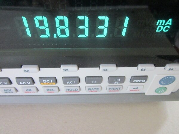
This is the measured average supply current for the breadboard circuit, which is reasonably consistent with the above.


image


Some scope for improvement there, if you felt inclined to play with it.


Finally, here's the open-loop response around the loop, from the simulator. This won't be very accurate, but it does nicely show the resonance peak due to the LC circuit and the fairly abrupt change in phase at that point [though you can see the effect resistance has in damping the peak].


image


If you found this interesting and would like to see more blogs I've written, a list can be found here:
https://www.element14.com/community/people/jc2048/blog/2018/10/24/jc2048-blog-index

  • Sign in to reply

Top Comments

  • jc2048
    jc2048 over 2 years ago in reply to jw0752 +5
    I didn't think it would work with an LM317, but it did. This is with an old Nat Semi part (it might not work with those from other manufacturers without changes, nor necessarily with more recent TI parts…
  • shabaz
    shabaz over 2 years ago +3
    Hi Jon, Very useful blog post. That's a significant amplitude oscillation! I'd also been wondering if a TL431 oscillator was possible, but the thought didn't occur to try to construct it into a Colpitt…
  • jw0752
    jw0752 over 2 years ago +3
    Hi Jon, I thought that was really cool. I have played with the TL431 a little but it never dawned on me that it could be an oscillator. Do you think we could make an LM 317 oscillate in a similar fashion…
  • jw0752
    jw0752 over 2 years ago in reply to jc2048

    Hi Jon,

    My hat's off to you. I mentioned the LM 317 with a bit of sarcasm in mind but then you work your magic and voila! Thanks, I promise not to dream up any more impossible tasks.

    John

    • Cancel
    • Vote Up +3 Vote Down
    • Sign in to reply
    • More
    • Cancel
  • jc2048
    jc2048 over 2 years ago in reply to jw0752

    I didn't think it would work with an LM317, but it did. This is with an old Nat

    Semi part (it might not work with those from other manufacturers without changes,

    nor necessarily with more recent TI parts).


    Here's the circuit, breadboard, and 'scope trace (the trace is with a coupling cap and

    a 10k load from the capacitor tap):


    image


    Edit: I got the drawing slightly wrong. The coil is 4.7mH, not 4.7uH. [It's the part that looks like a very fat resistor in the

    photograph below.]


    image


    image


    The LM317 is something like this as an equivalent circuit, so we can use it as a

    sort of very rough approximation to a JFET [for small signals - the analogy goes wrong

    for large signals, because the hard offset of the reference isn't the same as how the gate

    of a JFET would behave, but it seems to work ok for this]


    image


    The error term is the difference between the OUT and the ADJ [offset by 1.25V]

    terminals, and that then controls the current down through the pass element. The oscillator circuit

    is then analogous to a JFET common-gate amplifier arrangement.


    It results in a better sinewave than with the TL431, and it only takes 5mA from the supply.

    • Cancel
    • Vote Up +5 Vote Down
    • Sign in to reply
    • More
    • Cancel
  • DAB
    DAB over 2 years ago in reply to phoenixcomm

    Not quite that old, but still.


    DAB

    • Cancel
    • Vote Up +3 Vote Down
    • Sign in to reply
    • More
    • Cancel
  • jc2048
    jc2048 over 2 years ago in reply to phoenixcomm

    Thanks for that, Cris. The Wikipedia entry is fascinating.


    https://en.wikipedia.org/wiki/Dynatron_oscillator

    • Cancel
    • Vote Up +2 Vote Down
    • Sign in to reply
    • More
    • Cancel
  • jc2048
    jc2048 over 2 years ago in reply to jw0752

    That's an interesting idea. The trouble with all these devices is the way the power is sharing the same pins as the signals, so you need a way to get dc power to the part, whilst also allowing a circuit for the ac. The TL431, being a shunt regulator, sits much like a JFET or BJT would, so it's quite easy to see how it might be used [perhaps think of it as sort of like a very high gain transistor, with a 2.5V Vbe, but the kind of fT that an ancient germanium part might have had]. I'm less clear about a series regulator like the LM317. I'll have a think about it, but no promises (you might do better asking Shabaz or Doug).

    • Cancel
    • Vote Up +2 Vote Down
    • Sign in to reply
    • More
    • Cancel
>
element14 Community

element14 is the first online community specifically for engineers. Connect with your peers and get expert answers to your questions.

  • Members
  • Learn
  • Technologies
  • Challenges & Projects
  • Products
  • Store
  • About Us
  • Feedback & Support
  • FAQs
  • Terms of Use
  • Privacy Policy
  • Legal and Copyright Notices
  • Sitemap
  • Cookies

An Avnet Company © 2023 Premier Farnell Limited. All Rights Reserved.

Premier Farnell Ltd, registered in England and Wales (no 00876412), registered office: Farnell House, Forge Lane, Leeds LS12 2NE.

ICP 备案号 10220084.

Follow element14

  • Facebook
  • Twitter
  • linkedin
  • YouTube