


I wrote about adapting the PAN1780 headers into an Arduino compatible layout and the next step was to test it. I used one of my old data logger shields that was cloned from the Adafruit version, and everything seems to work fine (besides a hiccup on the firmware which I worked around for now by using the NRF52840DK board definition instead of my custom PAN1780 one). I was afraid that parasitic capacitance on the longish wire wrap leads would cause issues, but looks like they work fine.
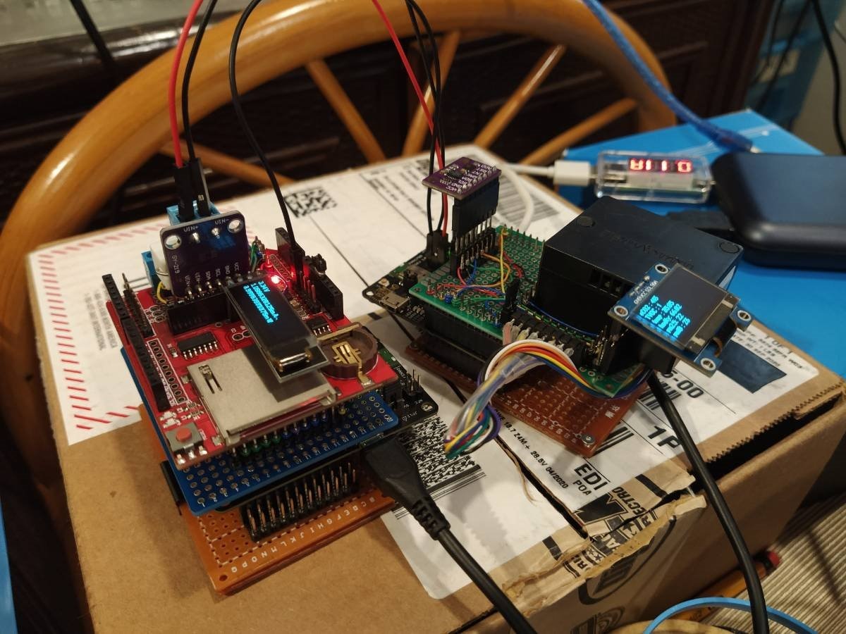
It's a small Volt-Ammeter based on the INA219 with some inspiration from a post talking about profiling current consumption, and being able to swap IC modules when needing to scale to different current ranges.
I'm using Espruino and it's also a good stress test for the library I wrote for the INA219; the benefit here is that it's all wireless (well, eventually it will be--I'm still deciding how to best expose the data). It's measuring the other PAN1780 of course (which gave interesting insight into how Panasonic Industry designed the power distribution in the eval kit).
I'm still doing the writeup for this section of my roadtest, so watch out for that  Putting this update here in case that one doesn't make the cut.
Here's the pin assignments, if anyone wants to follow along: