


I have been using TinkerCAD for a couple of years now to design the 3D printed parts I use in my Element14 projects. I haven't seen anyone else using this package so I thought I would give a 'live' overview of making a case for my Nano 33 BLE Sense based project. TinkerCAD isn't a full 3D design package so it has limitations but I find it simple to use and can create most if not all the shapes that I want - with a little bit of ingenuity. TinkerCAD works by adding or subtracting standard 3D shapes to create the desired outcome. I think I like it because it is a bit like solving one of those 3D puzzles of different shapes to be put together into a sphere or box. I wouldn't say I was all that good at using TinkerCAD yet and I am sure it has lots of features that I have not yet discovered but I am slowly learning more.
The Case
The case that I want is to hold a CR3032 battery in it's own battery holder with a Nano 33 BLE Sense. This was to be located in the nose cone of a water powered rocket but now that we are in lockdown I cannot really fire off a water powered rocket. Well, I could, but I probably wouldn't get it back. So, instead I have gone for a hand launched arrow type thing instead. I will not get the rapid initial acceleration expected from a water powered rocket but there will be some acceleration and the de-acceleration on landing might even be higher. Below is a sketch of the shape I am going to use, at least initially.
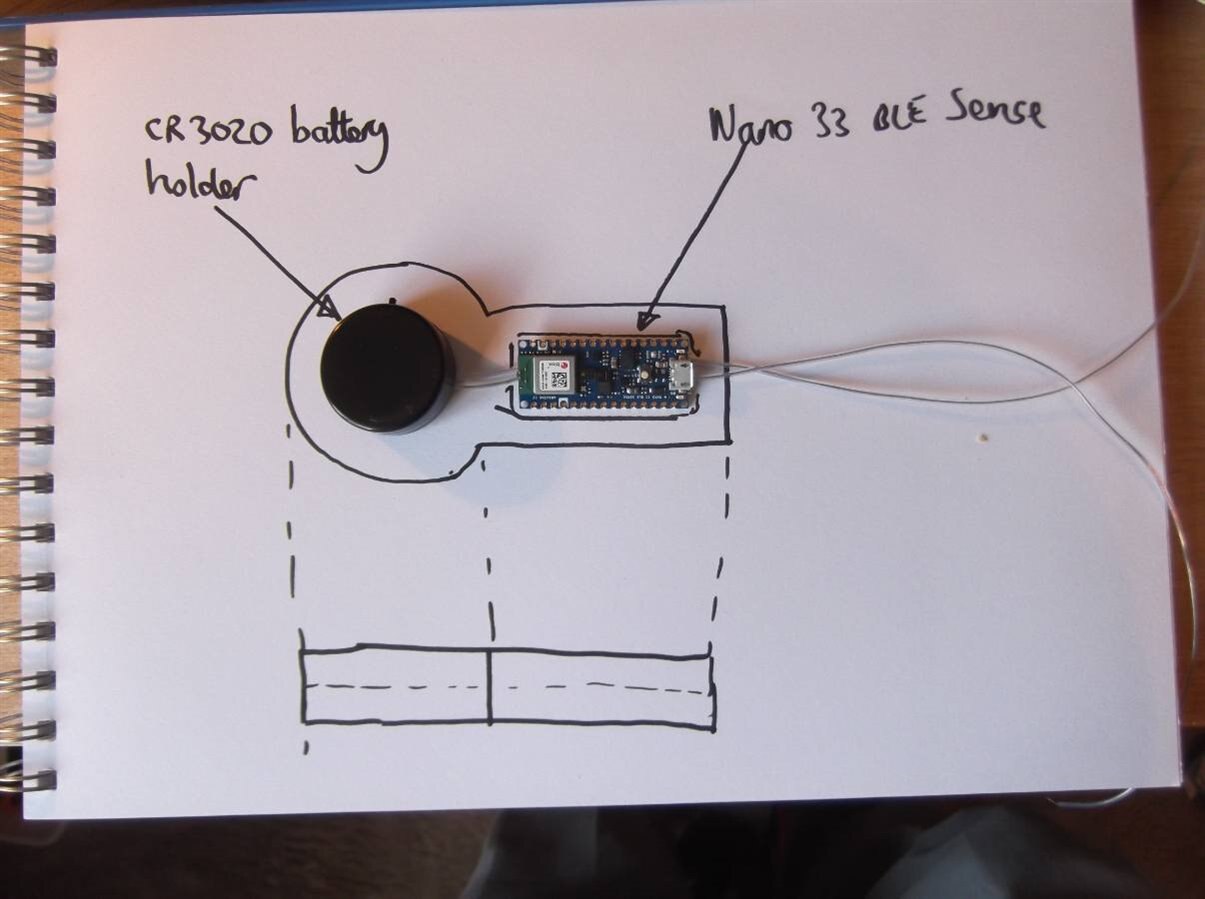
As far as I can tell at this time I will not need any additional components. The battery case has an ON/OFF switch and the Nano 33 BLE Sense has all the sensors I might need, plus the BLE communications link, assuming I can make it all work.
For the case I have gone for a rounded end to avoid concentrating the landing impact on a single point. The battery has been placed into the nose to make it nose heavy so that it will 'fly' through the air without too much spinning. I haven't added any fins at present but I can add some if the flight is not stable. Then I have gone for a flat shape rather than a full 3D sphere at the front, just to make the 3D printing easier and avoid having to use supporting material. I plan to use interference fits for the two printed parts of the case with the case split in two similar pieces which just fit together with an interference fit, or maybe a case with a flat lid. In fact, I think a case with a flat lid is a good idea so I will do that.
It is possible that with only using interference fits, the whole thing could come apart on impact but I do not think that will be a problem. If it is I will find some way of fixing parts together more permanently.
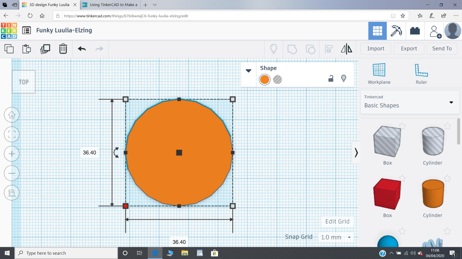
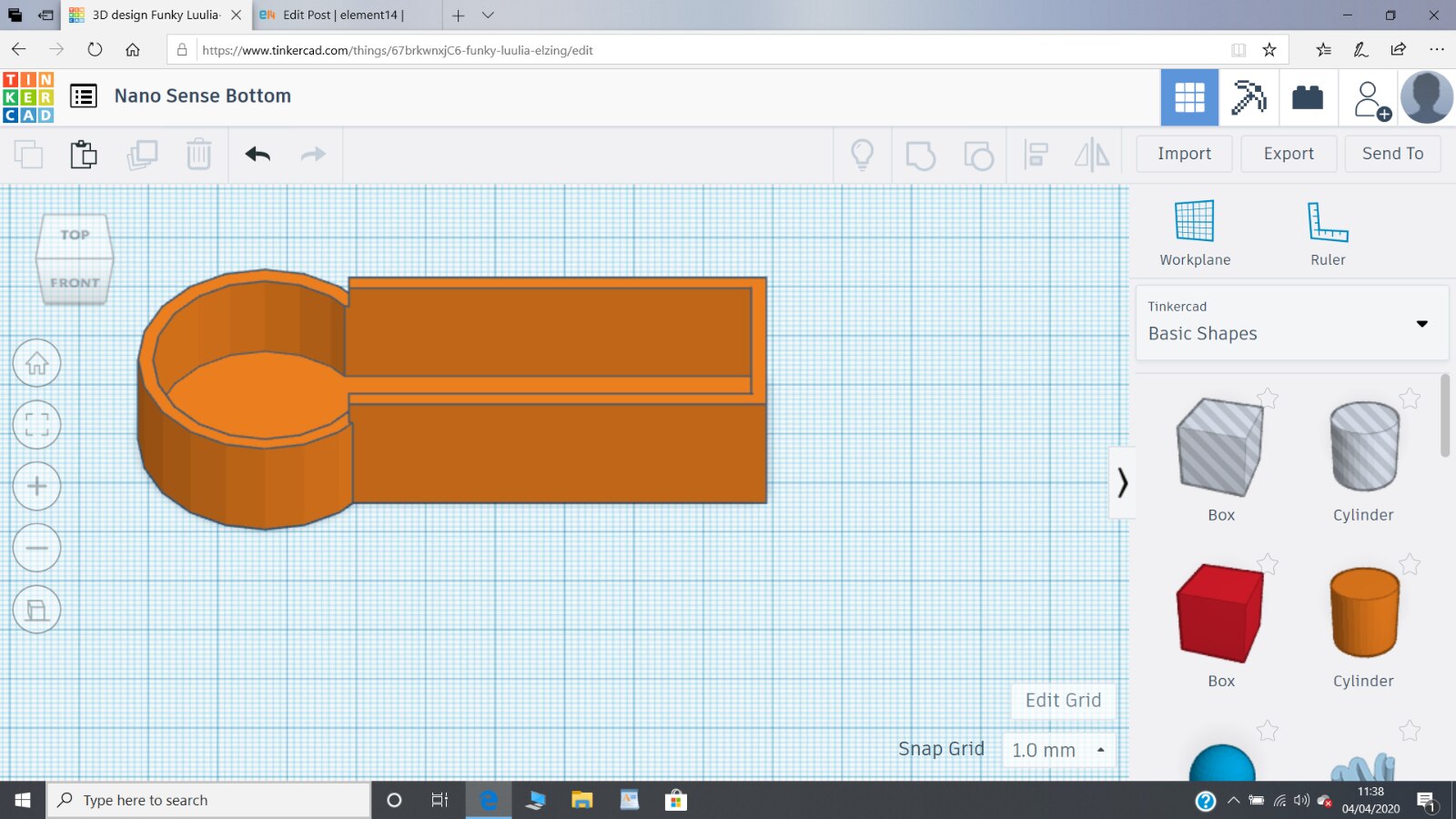
I am starting with a cylinder of diameter 36.4 mm. This is because the battery holder has a diameter of 32.4 mm and I want to have 2 mm thick walls. The battery holder is 12.8 mm high so the height of the case needs to be that, plus the case thickness (2mm), plus the space for the top piece (1.5 mm - why not), making a total height of 16.3 mm.
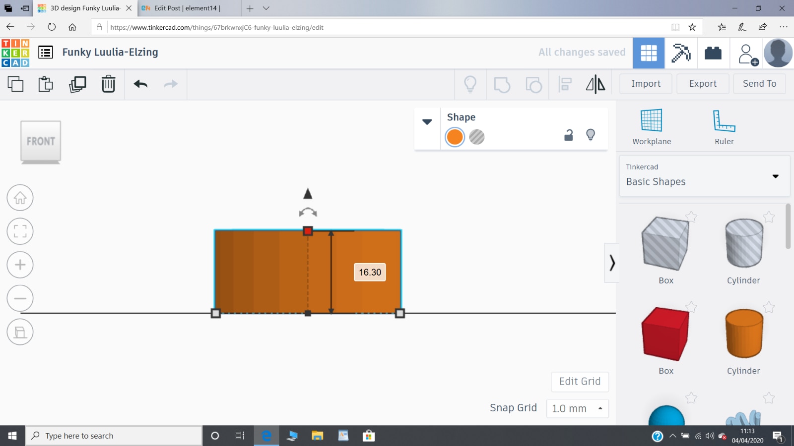
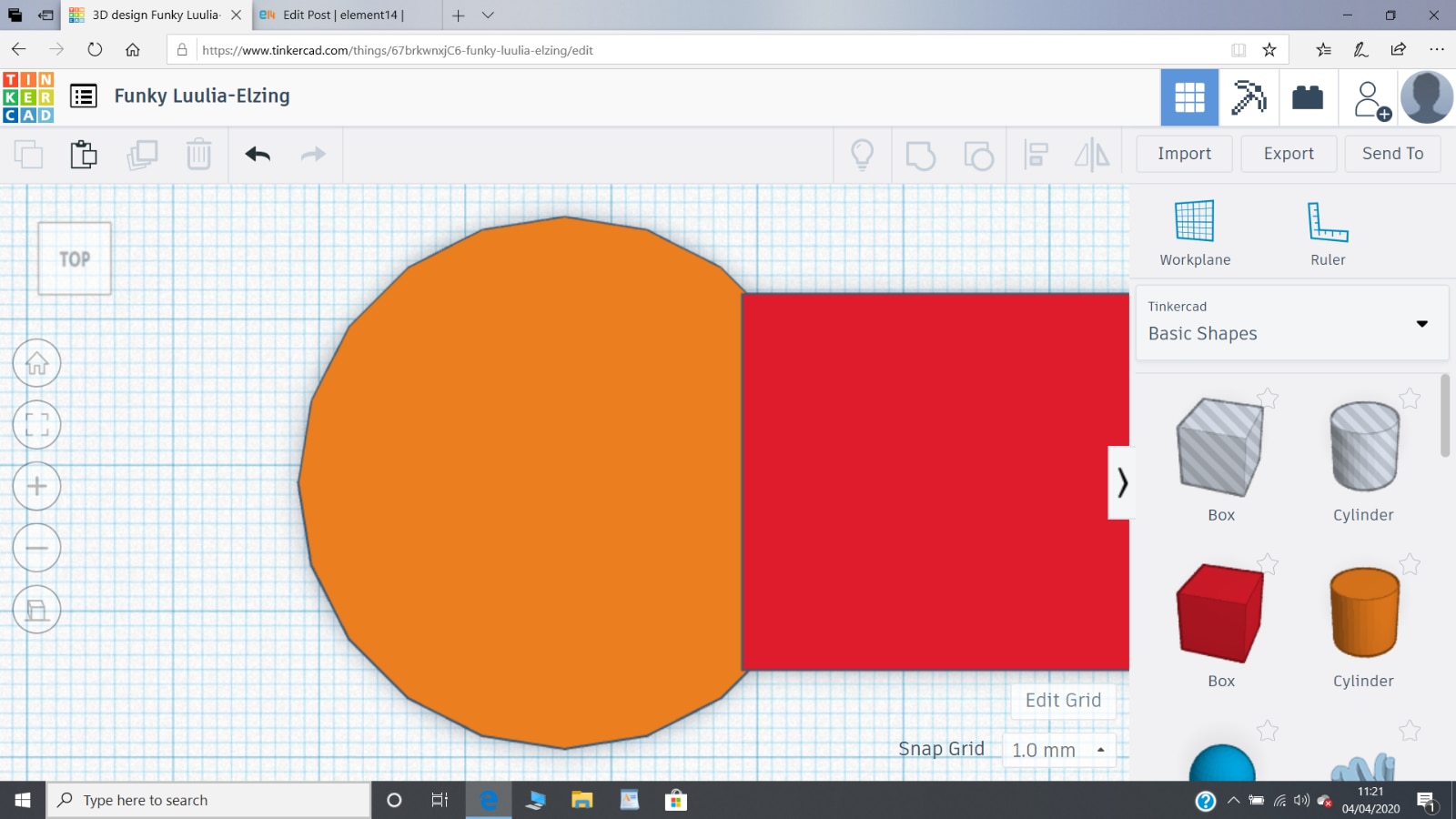
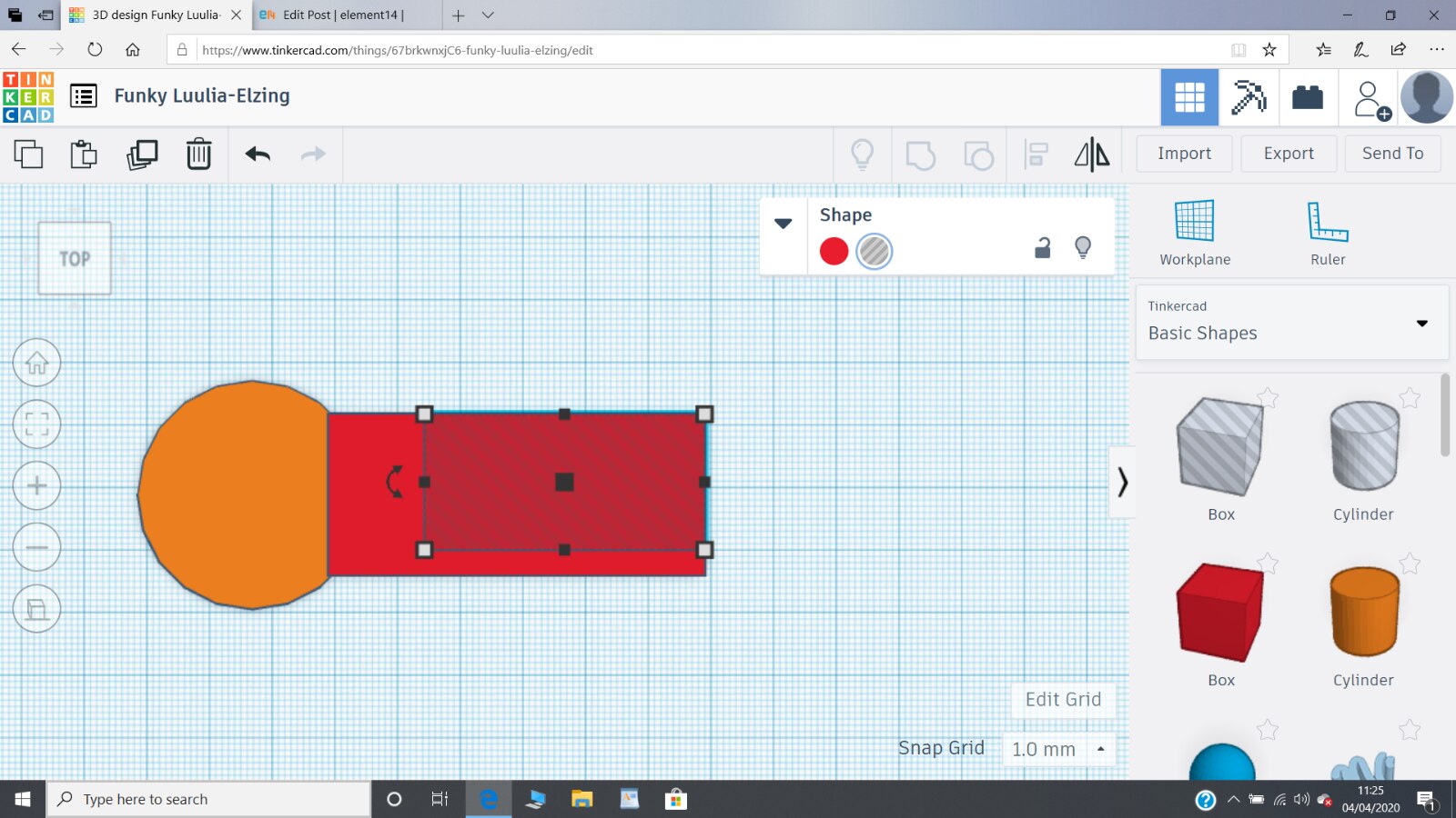
Next I will add an oblong which will hold the Nano Sense. The Nano Sense is 21.7 mm wide and 44.7 mm long so an oblong 25.7 mm wide (2 mm sides) and 60 mm long (allows a bit of leeway on the positioning of the Nano) seems about right. This will overlap with the cylinder. A close up view enables me to see that I have just enough overlap.
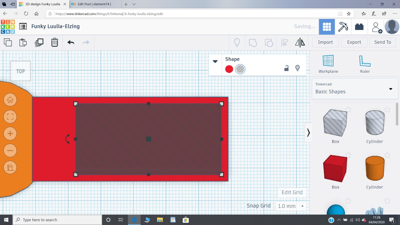
Before I 'join' these two parts together to make a single part I will just check the Nano Sense will still fit inside by making a 'hole' the size of the Nano and fitting it inside. I do this by adding a hole of the correct size (21.7 x 44.7) and positioning it to align perfectly with a top edge and end edge, see below, then I remove this 'hole' as it is no longer needed.
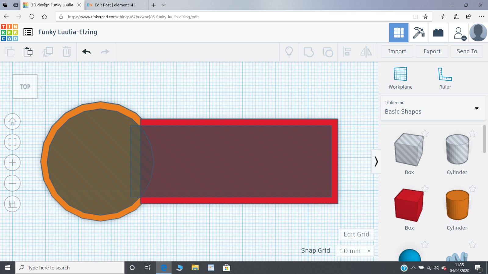
Then I can easily move it down 2 mm and left 2 mm so that it will be perfectly positioned and that has worked nicely.
There is plenty of room for the Nano Sense without encroaching on the space needed by the battery holder so I can extend the Nano Sense hole into the battery space. This doesn't matter as the next step is to add the battery holder hole and then make it one component. It is not that clear from the following diagram, but I have also raised the hole in the Z direction for the Nano Sense to create the 2 mm thick bottom for the casing.
I now add the hole for the battery casing, remembering to raise it 2 mm as well.
I think the bottom part of the case has now complete so I can combine all the cylinders, oblongs and holes together to make a single object.
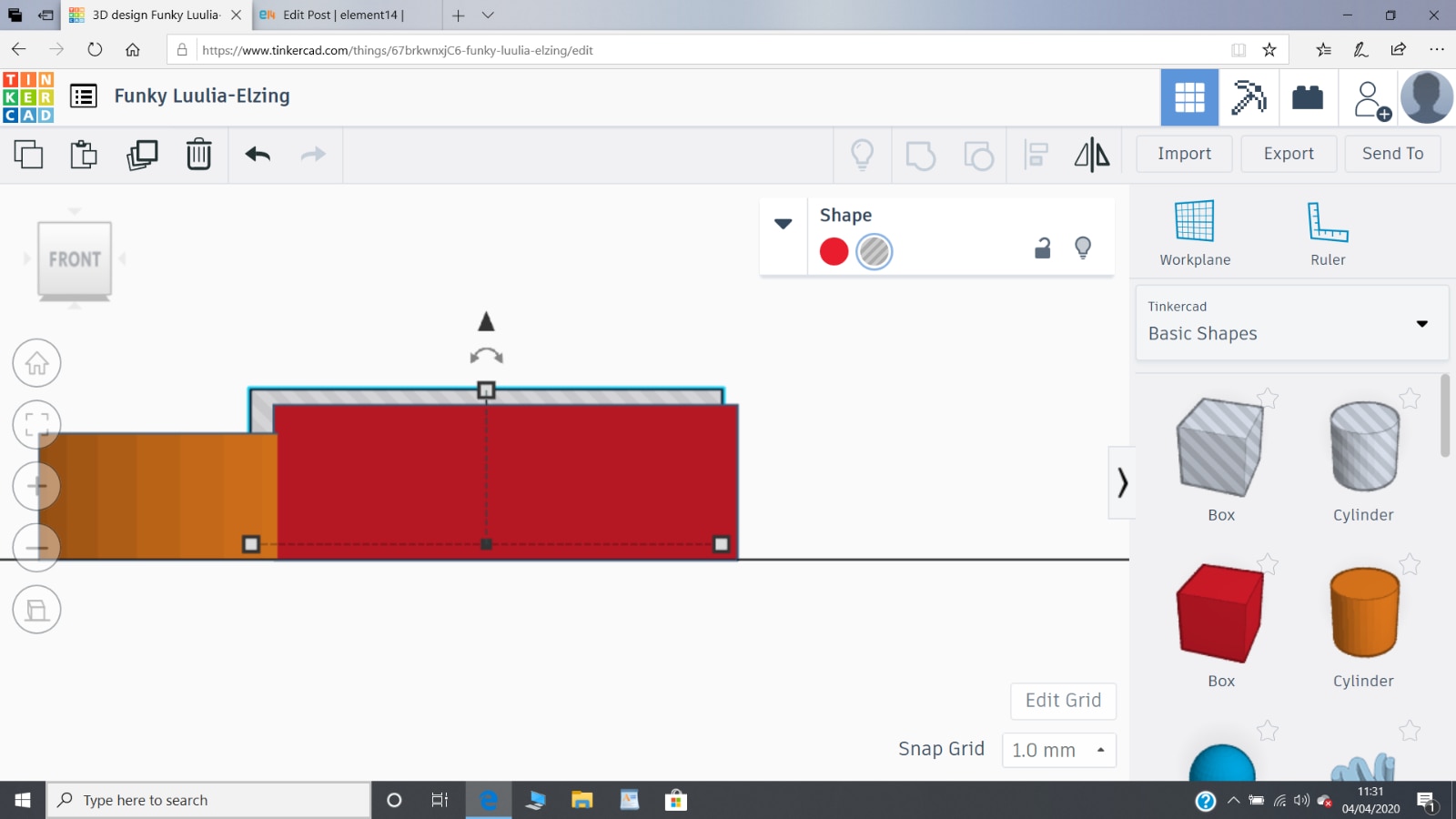
By looking at the part at an angle I can see that I have made a mistake, with the height of the oblong part. So, I just uncombine the parts, change the height of the oblong (the oblong hole does not need adjustment as it disappears anyway when combined) and the correct part can be seen below.
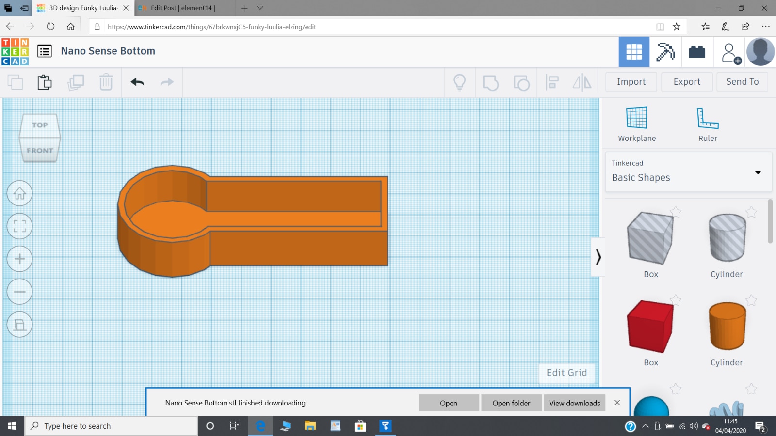
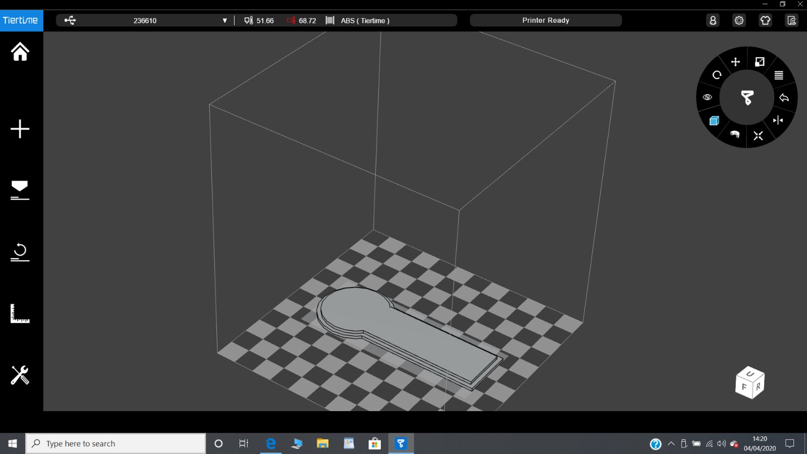
Now I can Export the STL for this 3D part and load it into my 3D printer, see below:
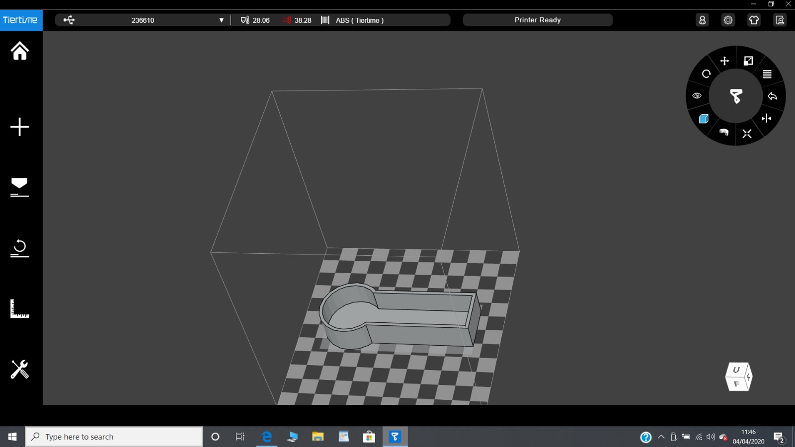
It can be seen from this illustration that this is probably the largest that I can make this case in one piece and still be able to print it. There is a little leeway and I could place it diagonally but my printer isn't that good at printing larger pieces - one of the corners tends to come away from the plate and the part deforms. Additionally, at this point I have realised that I have not put in anything that will stop the Nano Sense moving forwards when the rocket hits the ground. That is a simple solution, I just go back to TinkerCAD, uncombine the parts, add a small retaining wall and then recombine.
That took longer than I expected so the printer has now warmed up sufficiently and I can start the printing straight away. The printing is going to take 93 minutes so plenty of time to go and make a cup of tea and sit in the garden for a while.
I've sat in the garden and had my cup of tea and the 3D print is now ready.
Unfortunately I made a small mistake when measuring the width of the Nano Sense PCB. The correct value is 16.7 mm whereas I measured it to be 21.7 mm so the recess where the PCB should interference fit is too wide which means it will not be held securely. Additionally I did not leave space for the wires from the battery holder so the lid might not fit nicely. I will perform some 'surgery' on the lid part to make it all fit nicely. At this point I do not want to make another print as who knows what other mistakes I have made or what changes to the design I might have to make.
The Lid
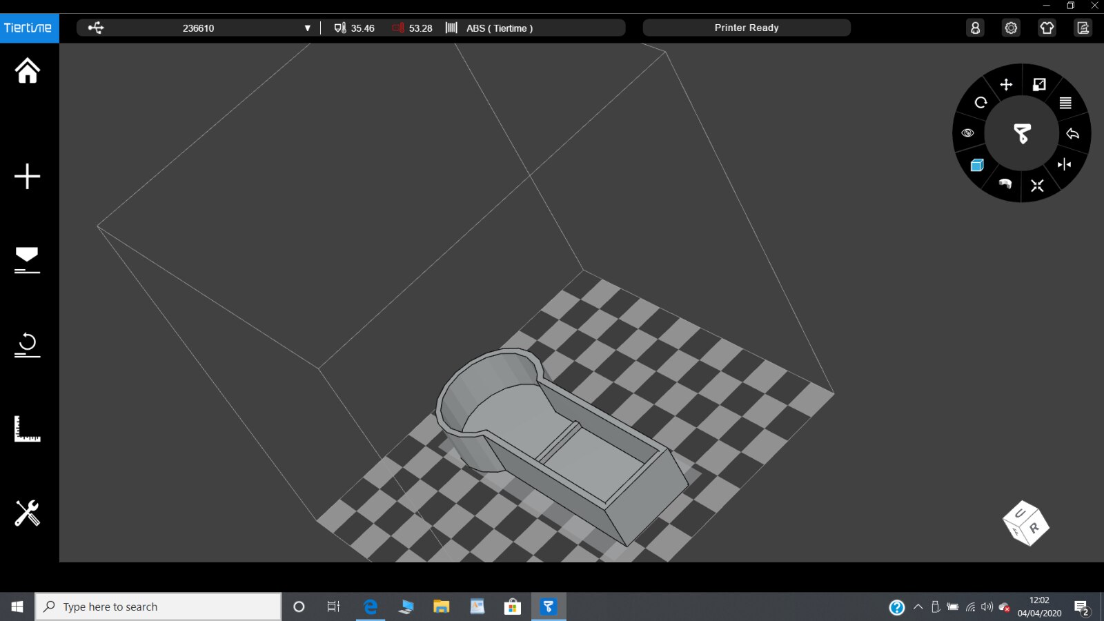
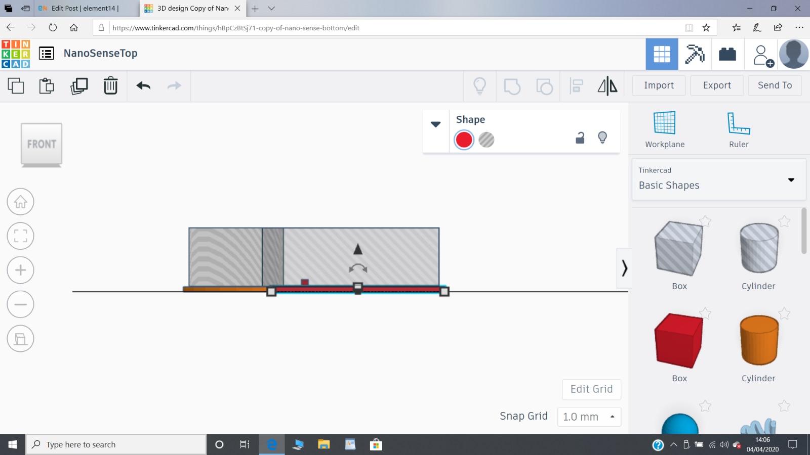
I know need to design the lid to fit onto the top of this bottom case. This is actually relatively easy. I want the lid to be an exact fit into the case so all I need to do is to make a duplicate of the Bottom part in TinkerCAD which I have named as NanoSenseTop and uncombine the various parts, as illustrated in the side view below.
Then I just convert the two hole parts into solid part and make their height 3.00 mm, as shown below.
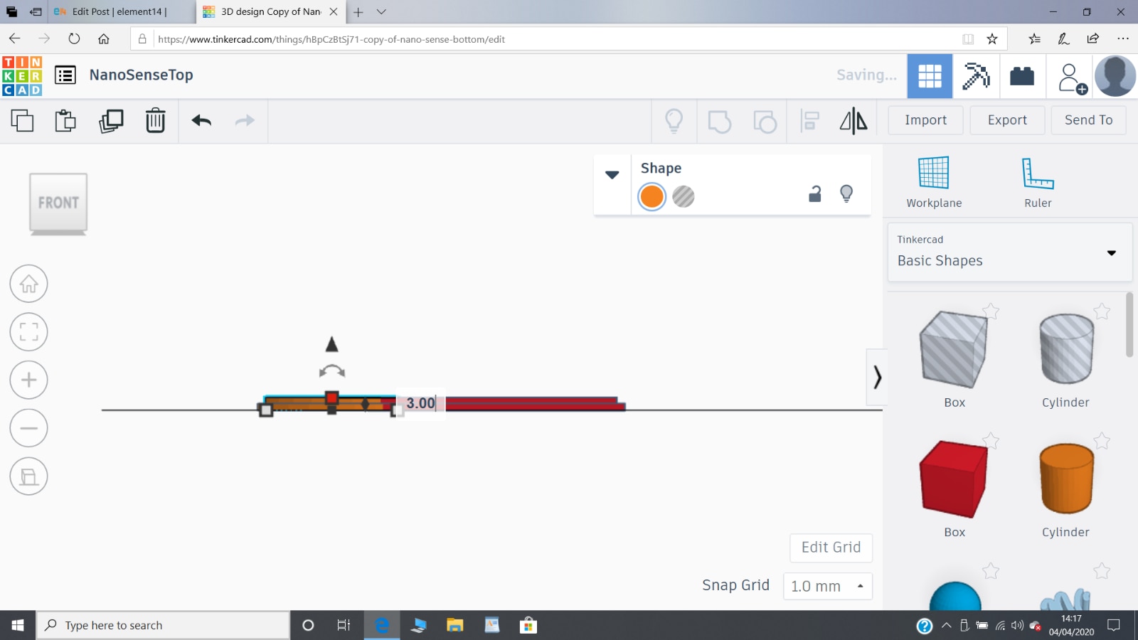
The previous 'holes' then become the solid that will exactly fit inside the bottom case and make a perfect snug fit. Well, that's the theory, let's see how the 3D print turns out.
Now to 3D print it (it will take 49 minutes) and see how good it is. Looks like time for more tea and sunshine.
Well, I've been in the sun and planted my early potatoes (actually they're a bit late now) and the Nano Sense Top has printed and been cleaned up. It fits perfectly, apart from the problem with the wires from the battery holder but with a bit of carving and sanding it should be possible to perfect that imperfection as well.
It's taken about six hours in all, but some of that was waiting for parts to finish printing and some was drinking tea and being in the sunshine. Not too bad.
Dubbie
Top Comments