element14 Community
element14 Community
    Register Log In
  • Site
  • Search
  • Log In Register
  • Community Hub
    Community Hub
    • What's New on element14
    • Feedback and Support
    • Benefits of Membership
    • Personal Blogs
    • Members Area
    • Achievement Levels
  • Learn
    Learn
    • Ask an Expert
    • eBooks
    • element14 presents
    • Learning Center
    • Tech Spotlight
    • STEM Academy
    • Webinars, Training and Events
    • Learning Groups
  • Technologies
    Technologies
    • 3D Printing
    • FPGA
    • Industrial Automation
    • Internet of Things
    • Power & Energy
    • Sensors
    • Technology Groups
  • Challenges & Projects
    Challenges & Projects
    • Design Challenges
    • element14 presents Projects
    • Project14
    • Arduino Projects
    • Raspberry Pi Projects
    • Project Groups
  • Products
    Products
    • Arduino
    • Avnet & Tria Boards Community
    • Dev Tools
    • Manufacturers
    • Multicomp Pro
    • Product Groups
    • Raspberry Pi
    • RoadTests & Reviews
  • About Us
  • Store
    Store
    • Visit Your Store
    • Choose another store...
      • Europe
      •  Austria (German)
      •  Belgium (Dutch, French)
      •  Bulgaria (Bulgarian)
      •  Czech Republic (Czech)
      •  Denmark (Danish)
      •  Estonia (Estonian)
      •  Finland (Finnish)
      •  France (French)
      •  Germany (German)
      •  Hungary (Hungarian)
      •  Ireland
      •  Israel
      •  Italy (Italian)
      •  Latvia (Latvian)
      •  
      •  Lithuania (Lithuanian)
      •  Netherlands (Dutch)
      •  Norway (Norwegian)
      •  Poland (Polish)
      •  Portugal (Portuguese)
      •  Romania (Romanian)
      •  Russia (Russian)
      •  Slovakia (Slovak)
      •  Slovenia (Slovenian)
      •  Spain (Spanish)
      •  Sweden (Swedish)
      •  Switzerland(German, French)
      •  Turkey (Turkish)
      •  United Kingdom
      • Asia Pacific
      •  Australia
      •  China
      •  Hong Kong
      •  India
      • Japan
      •  Korea (Korean)
      •  Malaysia
      •  New Zealand
      •  Philippines
      •  Singapore
      •  Taiwan
      •  Thailand (Thai)
      • Vietnam
      • Americas
      •  Brazil (Portuguese)
      •  Canada
      •  Mexico (Spanish)
      •  United States
      Can't find the country/region you're looking for? Visit our export site or find a local distributor.
  • Translate
  • Profile
  • Settings
Personal Blogs
  • Community Hub
  • More
Personal Blogs
Frank Milburn's Blog AIS Alarm - PCB Version 0.2
  • Blog
  • Documents
  • Mentions
  • Sub-Groups
  • Tags
  • More
  • Cancel
  • New
  • Share
  • More
  • Cancel
Group Actions
  • Group RSS
  • More
  • Cancel
Engagement
  • Author Author: fmilburn
  • Date Created: 7 Feb 2018 4:24 AM Date Created
  • Views 1552 views
  • Likes 9 likes
  • Comments 9 comments
  • daisy
  • smd
  • ais
  • state machine
  • pcb
  • msp430
Related
Recommended

AIS Alarm - PCB Version 0.2

fmilburn
fmilburn
7 Feb 2018

Project Objective: Develop an open source AIS Alarm that alerts sailors that a new marine vessel with AIS is within range


Over the weekend I modified the PCB design, submitted it for production, and started thinking about refactoring the firmware.  This post will show the new PCB design and outline some of the thinking that went into it.  A first pass at the state machine will also be introduced.


Here is a rendering of the new PCB that is now being manufactured:

image

The main changes are:

  • Removed the LED that was causing interferences with the side of the case completely.  I decided I could convey necessary information with blinks of different length rather than multiple LEDs - remains to be seen how well that will work.  Reduces BOM and cost.  I considered using SMD LEDs very seriously but in the end settled for the 5mm one used here because I wanted maximum brightness.
  • Moved the dAISy on the alarm board directly over the header on the radio.  Bought some short "Dupont" 0.1" headers and will try to connect the two boards that way rather than use ribbon cable.  Will tidy things up and make assembly easier but is a tight fit.  Somewhat more costly since they are non-standard headers.  This is something of an offshoot of the idea Gene suggested in my last post.
  • Moved the buzzer forward to remove interference and placed the programming header behind it.  The microcontroller is now closer to the radio which is undesirable.  Need to check if this materially reduces reception from the radio when the PCB comes back.


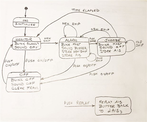
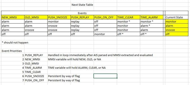
This is the simplified state machine both as a diagram and a table showing movement from one state to the next.  In the old design there were LEDs for on/off, alarm, and ship detected.  Now it is done with one LED.  This is probably close but I have to keep stopping myself from adding features (KISS).

image

image

The V0.2 board should be back by the end of next week.


I found someone who is willing to test it and give feedback when I am comfortable with the prototype.  It is a person who has sailed the Pacific on a small boat and is interested in looking at it.


Past Posts from this Project:

AIS Alarm

AIS Alarm - The Process

AIS Alarm - Prototype Hardware

AIS Alarm - Timers and GPIO

AIS Alarm - Prototype Code Outline

AIS Alarm - UART

AIS Alarm - First AIS Messages

AIS Alarm - First FRAM Storage

AIS Alarm - Debouncing Momentary Button Switches

AIS Alarm - FRAM Ring Buffer

AIS Alarm - Schematic

AIS Alarm - PCB Version 0.1

AIS Alarm - PCB Version 0.1 Arrived


References and Links:

WEGMATT LLC - dAISy AIS Receiver - low cost AIS receiver

Texas Instruments MSP430FR2xx FRAM Microcontrollers - Post No. 4

TI MSP430FR2111

Maximize the Sound from a Buzzer

  • Sign in to reply

Top Comments

  • fmilburn
    fmilburn over 7 years ago in reply to gecoz +4
    Hi Fabio, Thanks for examining my work critically - it is appreciated. You have found an omission in the state diagram. Also, I am a self taught enthusiast programmer so my work may not reflect standard…
  • shabaz
    shabaz over 7 years ago +3
    Hi Frank, Nice-looking board design! the entire project is looking really great. As for the board changes, I felt your pain, I too am currently battling with an enclosure, there is never enough room :…
  • gecoz
    gecoz over 7 years ago +2
    Hi Frank, I like this new version of the board, looks very neat. It is great you already found someone willing to test your prototype, I always find on-the-field testing one of the hardest part to cover…
Parents
  • gecoz
    gecoz over 7 years ago

    Hi Frank,

    I like this new version of the board, looks very neat. It is great you already found someone willing to test your prototype, I always find on-the-field testing  one of the hardest part to cover.

    I have a question about the snooze functionality though: why the triggering of time elapsed event makes the snooze state switch to monitor? This creates a path where you can end up in the monitor state without passing by the off state, is this wanted?

    I would have expected the snooze to have only 3 allowed states as next state: snooze, alarm and off, with the time elapsed event moving the state from snooze back to alarm (a bit like it happens with alarm clocks).

    Looking forward to see the board 0.2 completed.

    Fabio.

    • Cancel
    • Vote Up +2 Vote Down
    • Sign in to reply
    • More
    • Cancel
Comment
  • gecoz
    gecoz over 7 years ago

    Hi Frank,

    I like this new version of the board, looks very neat. It is great you already found someone willing to test your prototype, I always find on-the-field testing  one of the hardest part to cover.

    I have a question about the snooze functionality though: why the triggering of time elapsed event makes the snooze state switch to monitor? This creates a path where you can end up in the monitor state without passing by the off state, is this wanted?

    I would have expected the snooze to have only 3 allowed states as next state: snooze, alarm and off, with the time elapsed event moving the state from snooze back to alarm (a bit like it happens with alarm clocks).

    Looking forward to see the board 0.2 completed.

    Fabio.

    • Cancel
    • Vote Up +2 Vote Down
    • Sign in to reply
    • More
    • Cancel
Children
  • fmilburn
    fmilburn over 7 years ago in reply to gecoz

    Hi Fabio,

    Thanks for examining my work critically - it is appreciated.  You have found an omission in the state diagram.  Also, I am a self taught enthusiast programmer so my work may not reflect standard practice and I would like to improve in that area.


    The Next State Table better reflects what I want to do.  If a ship has been detected and the user hits snooze it is assumed they have investigated and determined that collision is not imminent.  Provided the user does not turn the unit off (or a new ship is detected which leads to ALARM) it will stay in the SNOOZE state for fix period of time shown as TIME ELAPSED in the diagram.  There should actually be two arrows associated with TIME ELAPSED, the second of which goes to the ALARM state.


    As shown in the table, the two events associated TIME ELAPSED are TIME_CLEAR and TIME_ALARM.  Lets say the TIME ELAPSED is 15 minutes.  If 15 minutes passes and no transmissions from the "snooze" ship have been received in say the last 5 minutes then it is assumed that the ship is out of range.  In that case, the next state will be MONITOR and we keep looking for new ships.  On the other hand if transmissions are still being received then the next state will be ALARM and the user should investigate before hitting snooze again.  At this point I have not determined what the default times should be.


    Regarding passing through OFF, the idea is to never go to OFF unless the user selects to do it.  In my current scheme, the only way to exit OFF is for the user to turn it back to ON in which everything gets reinitialized and I don't want that.


    Thanks again for the comment.  I will repost the state machine after I have thought through it some more and start laying out code.  If you still see a way to improve what I am doing, please comment!

    • Cancel
    • Vote Up +4 Vote Down
    • Sign in to reply
    • More
    • Cancel
  • gecoz
    gecoz over 7 years ago in reply to fmilburn

    Hi Frank,

    Thanks for explaining to me, now I think I understand what the snooze state does and how you are using it.

    I think you probably can get away using only one event for the timer, the TIME_CLEAR event. The reasoning behind is that, while in the SNOOZE state, which I assume will start the timer, you can only exit the state if a new ship is detected (NEW_SHIP event), in which case you move back to the ALARM state, or if the time is elapsed, in which case you either move to ALARM, if the old ship is still detected (OLD_SHIP event), or you move back to MONITORING if no detection occurred (TIME_CLEAR event).

    You are doing a superb job with this project, and definitely you should not underestimate your programming skills.

    Keep up the great work.

    Fabio.

    • Cancel
    • Vote Up +2 Vote Down
    • Sign in to reply
    • More
    • Cancel
  • fmilburn
    fmilburn over 7 years ago in reply to gecoz

    Thanks Fabio and much appreciated.

    • Cancel
    • Vote Up +2 Vote Down
    • Sign in to reply
    • More
    • Cancel
element14 Community

element14 is the first online community specifically for engineers. Connect with your peers and get expert answers to your questions.

  • Members
  • Learn
  • Technologies
  • Challenges & Projects
  • Products
  • Store
  • About Us
  • Feedback & Support
  • FAQs
  • Terms of Use
  • Privacy Policy
  • Legal and Copyright Notices
  • Sitemap
  • Cookies

An Avnet Company © 2026 Premier Farnell Limited. All Rights Reserved.

Premier Farnell Ltd, registered in England and Wales (no 00876412), registered office: Farnell House, Forge Lane, Leeds LS12 2NE.

ICP 备案号 10220084.

Follow element14

  • X
  • Facebook
  • linkedin
  • YouTube