


Introduction
In my last post I described a simple circuit that produced a reasonably accurate 10 mA current source to allow measurement of DC resistance down into the milliohm range. I received a number of helpful suggestions on how to improve the circuit as well as great discussion on selecting precision parts. This post will outline several approaches I have considered on how to proceed. As a refresher, here are the design objectives originally posted:
- Inexpensive
- Can run off batteries
- No more than 10 mA to DUT
- milliohm level accuracy
- Range 1 milliohm to 10 ohms
The Basic Blocks
As is the usual case in electronics, and for that matter most engineering problems, there are many different approaches and potential solutions. For this project we want to provide a constant current across the Device Under Test (DUT) and measure the voltage drop across it to determine the resistance of the DUT using Ohm's Law. For purposes of discussion here is a simplified block diagram which omits certain details such as the power source.

The four blocks are:
- SET: This sets a value (in this case voltage) which will be use for comparison by the control block so see if the operating point needs adjustment
- CONTROL: The control block compares the set point to the sensing element operating point and makes corrections as needed
- MEASURE: This block measures the voltage across the DUT (shown as a resistive load) and reports it to the user in either ohms or voltage that can be converted to ohms.
- SENSE: The sense block feeds the actual operating point back to the control block so corrections can be made as needed.
It is worth noting again that this is just one way of approaching the problem. For example, we could replace the three blocks on the left with a DC power supply with current limiting capability. The measurement is easily done with a multimeter and would meet all the objectives above except for batteries. But where is the fun in that :-) Below is a summary of the design and areas for improvement.
SET Block: In the last post I used resistors to form a voltage divider to form the set point. The accuracy is then dependent on the voltage of the power source as well as the precision of the resistors and their temperature coefficient. There are precision voltage sources that could be used to replace the voltage divider. I have on order a LT6654BIS 1.25V, 0.1% +/- 10ppm/C voltage reference.
CONTROL Block: I used a TLV2462a rail to rail op amp with negative feedback to drive the current to 10 mA. Chopper op amps reduce the offset and temperature drift thus potentially improving accuracy. The set point could be moved to obtain better accuracy. I have on order MAX9619A and MCP6N16 op amps.
MEASURE Block: I used a good quality bench meter and don't expect to improve on that. In fact I will probably replace it with a less capable instrument to meet the objectives above. I have an inexpensive 0-10V 5 digit meter on order from China but it will take a while to get here and who knows how good it will be. I also ordered materials to make proper Kelvin test leads. I am considering a microcontroller with ADC and this will be discussed in greater detail below.
SENSE Block: I used a 1% tolerance resistor. Resistors with better temperature coefficients and improved tolerances can be substituted. I have on order 0.1% and 0.5% resistors with low temperature coefficients.
It should also be pointed out that there are other ICs that can be used and I have ordered the LM334 and TL431A. But one of the originally unstated objectives is to learn more about op amps and that will be where I focus my efforts.
Microcontroller and ADC Measurement
I recently participated in the TI Robotic Systems Learning Kit Road Test which uses the MSP432P401 microcontroller which per the datasheet has a 16 bit SAR ADC. The manual calls it the ADC14 module. I ordered a second MSP432P401 LaunchPad so that I could play around with it some more. The MSP432 has a number of code examples available and I used the differential ADC example almost unchanged. I was at the edge of the ADC range and there was quite a bit of bouncing around so I added averaging. Here are the results as seen in the CCS debug window:
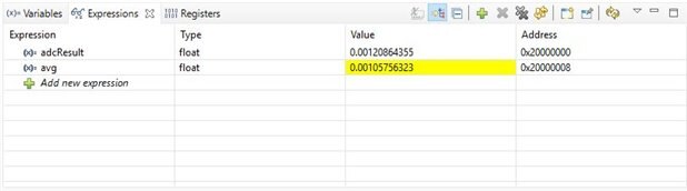
The variable adcResult holds the most recent value and the variable avg contains the average of 25 readings (highlighted in yellow). To get the resistance of the wire being measured multiply by 100 which gives 0.1058 ohms. Not surprisingly it is not as good as my bench meter which reports 0.0941 ohm in the most accurate configuration I have devised to date. It is however much better than a two wire multimeter alone.
Using a microcontroller is nice because some of the necessary calibration might be done in software and the conversion to ohms is easily done for display. It would also be possible to increase the measurement range of the device by multiplexing different sensing resistors and thus current. But it also adds complexity and may not be as accurate. I could buy a separate ADC with improved resolution and accuracy but they are expensive. I haven't quite given up on the idea yet though.
Next Steps
I have on order the components to create a more accurate device but it will probably be necessary to increase the current up to say 100 mA to increase the voltage drop across the DUT to get true milliohm resolution. I question whether this is a worthwhile device to actually construct in final form as I don't have frequent need to make these measurements. And if I do it is not too much problem to set up the power supply as a constant current supply and use the bench multimeter to measure the voltage drop across the DUT. Nonetheless this is a great learning exercise and I have alternate ideas for the components if I decide not to build a permanent instrument.
I greatly appreciate input from michaelkellett, shabaz, and jc2048 on ideas for improvement - see the comments at the bottom of my previous post. Thanks also to jw0752 for posting his constant load project which has great discussion on op amp circuit behavior and a very nice build. As always, further comments, suggestions, and corrections are appreciated.
Top Comments