


I am posting my initial impressions of the Multicomp Pro Handheld LCR MeterMulticomp Pro Handheld LCR Meter. My objectives are to get familiar with the capabilities and use of the meter, do some comparisons to other instruments in my possession, and summarize my impressions in a way that might prove useful for other electronics enthusiasts.

Background
I am constantly trying to upgrade my bench and this is the first really capable LCR meter I have owned. It was definitely a want as opposed to a need but after winning a Project14 contest a while back I was able to obtain it. My interests lie in the relatively complex way that passive components can behave and how they differ from ideal behavior. Among the areas I have investigated out of curiosity are the measurement of resistance in the milliohm region, capacitor ESR, and capacitor variance with frequency.
Two other LCR meters with similar capability often seen are the Der EE DE-5000 and various versions of BK Precision handheld LCR Meters - e.g. the top of the line 880. These sell for approximately $100 and $330 respectively with lower cost versions of the BK Precision meter available. I looked at their specifications and read reviews before ordering my Multicomp Pro LCR meter to get an idea of what else is on the market. Multicomp Pro is a relatively new brand for Farnell / Newark and I only recently came upon this meter. The current price at Newark is $195.
I wanted a meter with high resolution, good accuracy, multiple test frequencies, 4-wire measurement capability, auto ranging, wide measurement range, and all the measurement parameters you can get on an LCR meter. I want it all!
Specifications
Credit: specifications from Farnell website: 2899698.pdf (farnell.com)
First Impressions
The LCR meter came nicely boxed and undamaged. The meter has a nice zip up case that contains 2-wire test leads, a short circuit shunt, Type-C USB cable, and power adapter.

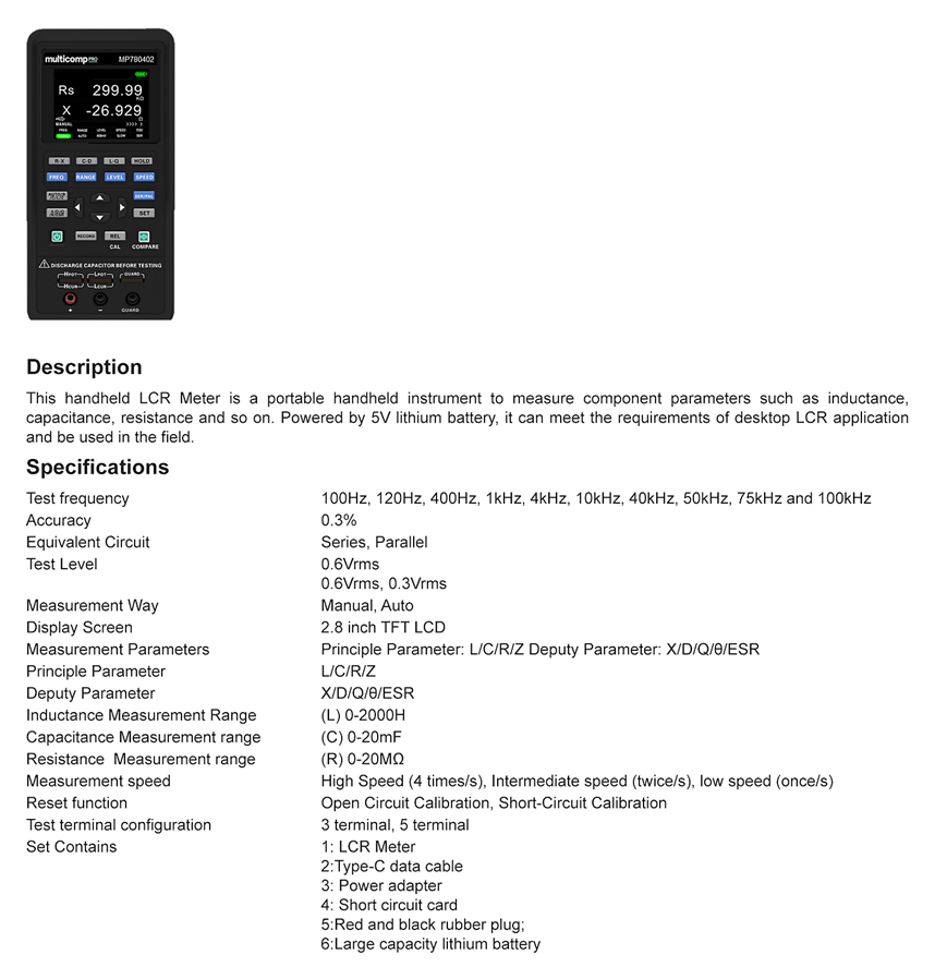
This is a large meter. I was surprised at how large. Very large  It feels sturdy and substantial. It takes it a short while to boot up and then there is a rather faint beep.
Before going further note that this is a rebranded Hantek 1833C. I was able to determine this by querying *IDN? with SCPI.
Front
The display is a 2.8 inch TFT LCD that looks nice with white lettering on a dark background. The primary and secondary functions are easy to read although the viewing angle is not as good nor is it as legible as some of my other meters. Still acceptable though. The backlighting is adjustable and good. The display also shows other parameters in a smaller font that is still legible provided one is no further away than they might be while reading a book. It is hard to photograph and the actual display is of even contrast and looks nicer than my attempt to capture it below.

There are lots of buttons and a keypad. The buttons are squishy, not clicky. Rather than go through them in great detail, here is a link to the user manual: 3154931.pdf (farnell.com). A greatly abbreviated overview is given below.
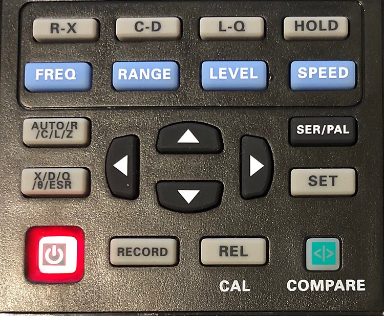
The top row of buttons allows the user to go straight to commonly used display modes and to hold the current reading. As an example of mode, the R-X button will display resistance as the primary parameter and impedance as the secondary parameter.
The second row of buttons allows setting of:
- frequency from 100 Hz up to 100 kHz
- manual measurement range
- RMS voltage level of 300 or 600 mV
- fast (4 Hz), medium (2 Hz), and slow (1 Hz) measurement speeds
The upper white button to the left of the arrow keys allow the primary parameter to be automatically or manually set (resistance, capacitance, inductance, and impedance). The white key below it sets the secondary parameter (reactance, dissipation factor, quality factor, phase angle, and equivalent series resistance). To the right of the arrow keys the black button allows measurement to be in either series or parallel equivalent modes. The set key allows language, display brightness, boot state, and the beeper to be set as well as displaying device information.
The arrow / cursor keys allow navigation through the row of parameters shown at the bottom of the display. These can be used to achieve the same results as using the buttons.
Just below the arrow keys are the power switch, record button (records min, average, and max when in a manual mode for the last 10 tests), and the REL and COMPARE keys which are used to calibrate the instrument. The COMPARE key can also be used to compare components to expected nominal values within a user selected range of "good".
Hurray! This meter has real 4-wire / Kelvin capability plus guard in addition to the standard jacks.
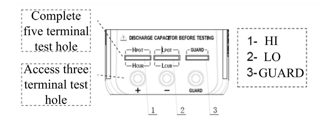
Credit: User Manual 3154931.pdf (farnell.com)
I found that when inserting small capacitors into the Kelvin slot it was possible to insert one leg incorrectly and get a bad reading. In that case it might be best to use the alligator clips that come with it although they aren't 4-wire. I'd like to fit some Kelvin probes to the meter but Newark does not list them. I intend to make my own.
Right Side
There is a flip open rubber cover that exposes the USB C. The USB C plug is atypically long and a standard plug won't reach all of the way. Don't lose that USB C cable! USB C is used to both recharge the battery and communicate over serial with a computer. The batteries are 18650 so they could be replaced in future. There is also a snap out plastic cover for something that isn't installed.
Back
There isn't that much to see here. I like the angle that the tilting stand gives. When tilted up the meter has to be held with one hand while buttons are pushed, else it will slide. There isn't an obvious way to get inside but I'll come back to why I didn't bother in a minute.

Top, Bottom, and Left Sides
There is an indentation and it is clear the enclosure is being used for multiple different instruments. It turns out that a hand held oscilloscope also uses this case and the indents are for BNC connection. The bottom and left side are unadorned.
Manual
No paper was provided and it is accessed online or can be downloaded in PDF form. It seems comprehensive.
Section 2.7 labeled Firmware Update of the manual seemed poorly done and I chose to ignore it. It instructs the user to download the tool "DfuSe Demo v3.0.5" and install it without giving a link. When I did a search it turns out this is a ST USB upgrade extension. I couldn't readily see the version listed in the manual on the ST site and the ST manual was too much to bother with that late at night. Windows 10 eventually installed the device after churning around a bit so I haven't revisited this.
In addition to a reasonably good description on how to use the instrument there is a complete set of tables giving accuracy for parameters at various ranges and measurement frequencies. For example, here are capacitance and dissipation for frequencies 100 to 400 Hz and all ranges along with the recommended equivalent mode.
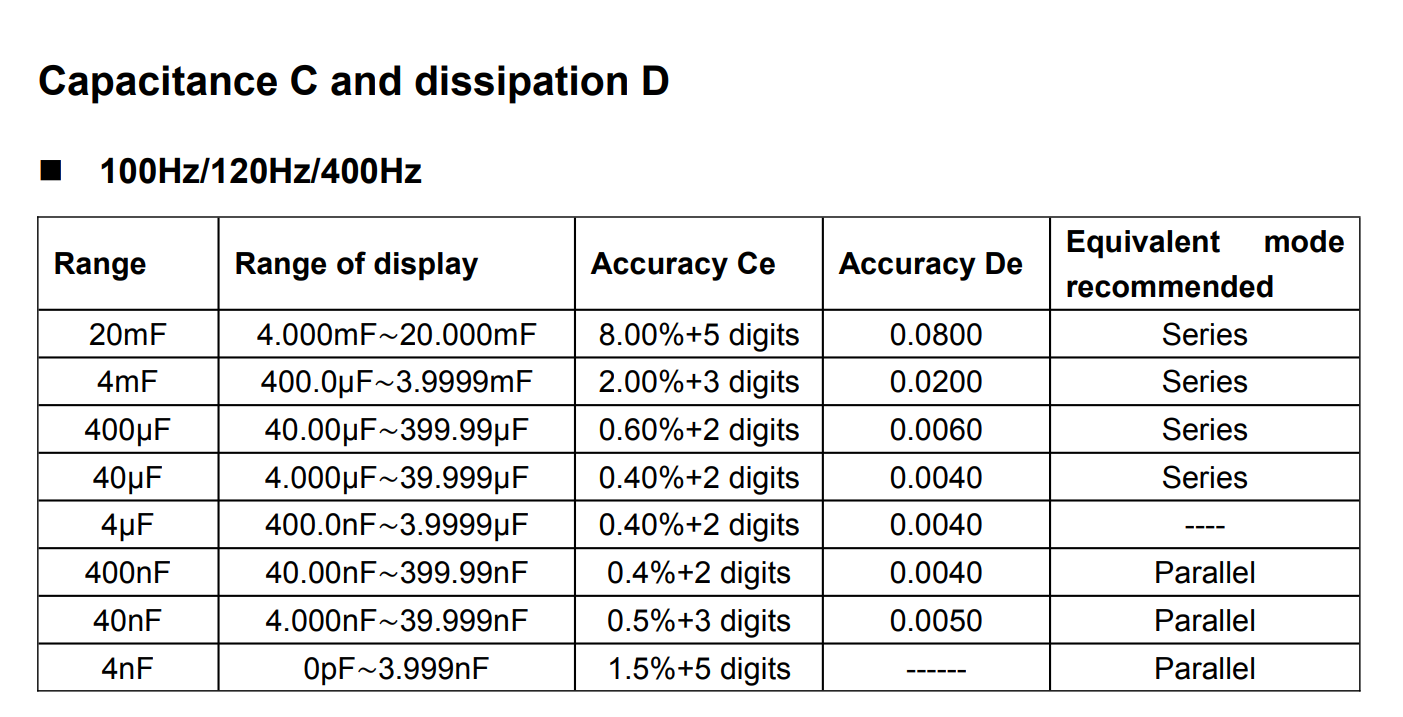
Credit: User Manual
Similar tables are available for other parameters, frequencies, and ranges and another example for impedance is shown below. The bottom end of the impedance range at 100 Hz is 0.4 ohms, shows 4 digits, and is accurate to 4% + 3 digits. That is pretty impressive but see my comments on measuring resistors.
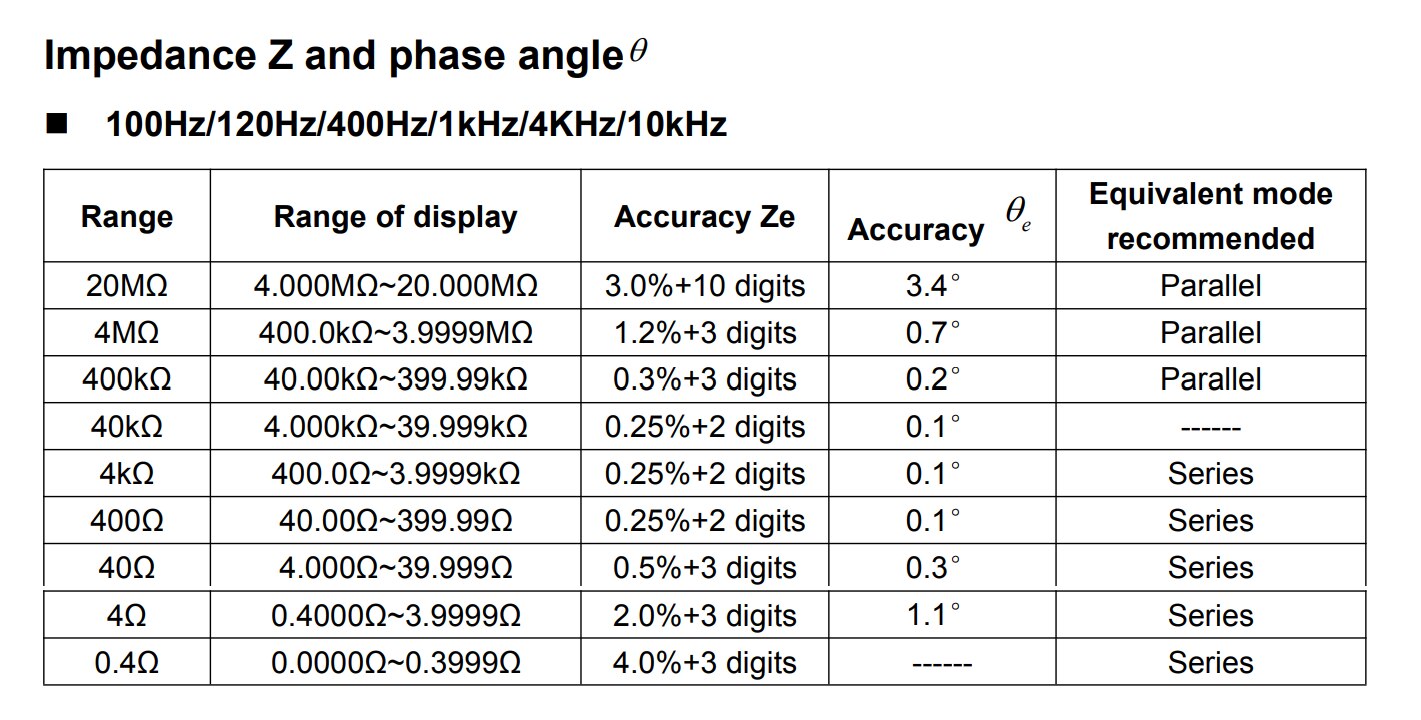
One thing I like about the BK Precision 880 is that it can automatically select the recommended equivalent series or parallel mode, a feature not available on the Multicomp Pro which is the kind of thing I am apt to forget to do. A feature not present on this instrument but available on the others is a DC setting for resistance. I don't consider that much of an issue for my use.
The manual also gives an account of communication using SCPI and has a complete command reference.
Time to Try It Out!
This not a comprehensive review and the capabilities of this LCR exceed anything else I have with the exception of pure resistance so I'm just going to learn to use it and compare it where I can to other instruments in my collection.
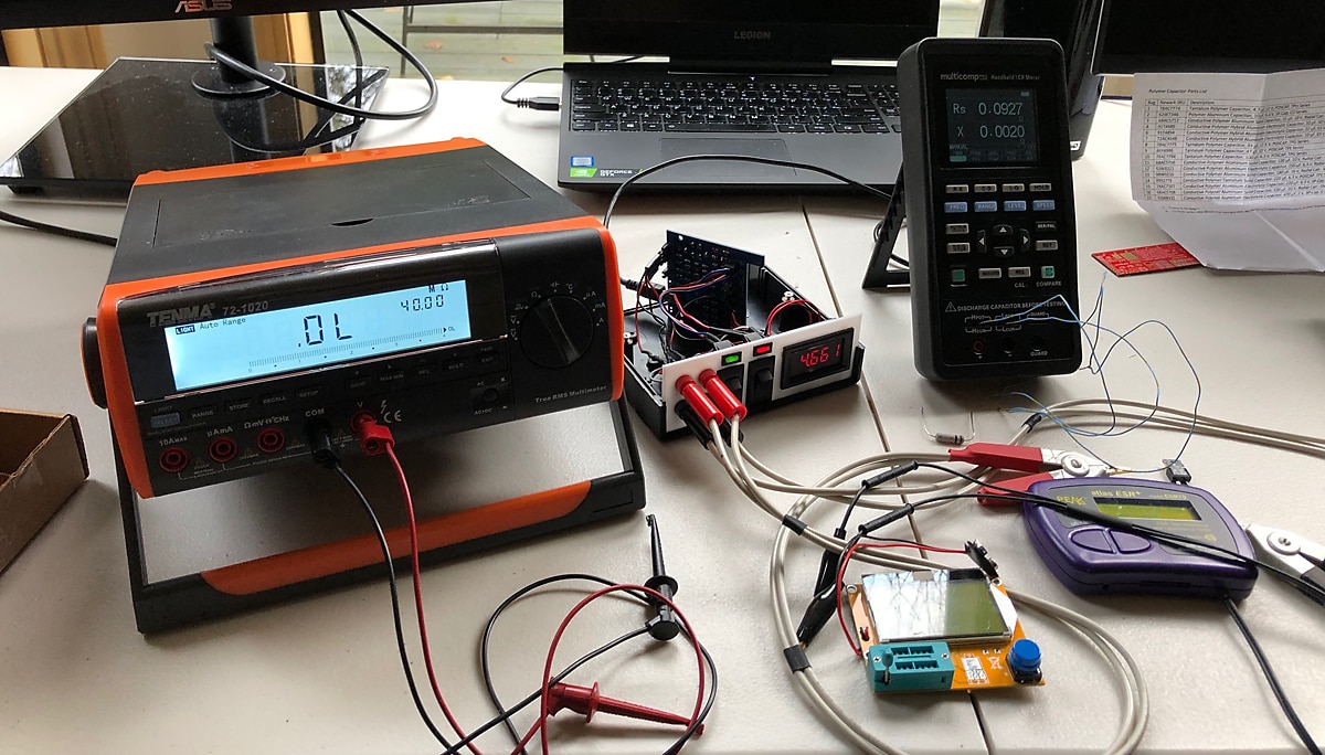
The bench multimeter on the left is a Tenma 72-1020Tenma 72-1020 and will be used for resistance and capacitance checking. The homemade instrument just to the right of it that is open (I'm about to build a new one) is a Milliohm Meter designed here on element14, the Multicomp Pro Handheld LCR MeterMulticomp Pro Handheld LCR Meter is to the right of it, and below that the purple instrument is a Peak ESR70Peak ESR70 capacitance and ESR meter. The yellowish orange device center bottom is one of the inexpensive multifunction transistor testers that can be bought off eBay or on Chinese sites.
Calibration
Calibration of the Multicomp Pro takes a few minutes to compete and is done in both open and closed modes. The meter cycles through all frequencies and ranges. It must be done in manual mode.
SCPI
Communication is over USB-C and the meter shows up on my Windows 10 machine as a USB Serial Device but initially gave an error. When the error checker was ran it did something and came back asking me to restart my machine. I did and started up Putty. The manual doesn't give the Baud rate. 9600 doesn't work but 2400 Baud seems to so I'm in. When the command *IDN? is issued the following is returned:
Hantek 1833C Handheld LCR Meter,20200602AM,CN2029021000865,1
Interesting. It is a rebranded Hantek instrument. When I did an internet search it turns out the Hantek version is selling for $181 on eBay shipping from China. There is also a review by VoltLog and he does a teardown so I don't have to: Hantek TO11 1832C LCR Meter Review & Teardown | Voltlog #303 – VoltLog
VoltLog's teardown reveals that the instrument uses 18650 batteries that could be replaced in future which is nice.
All the SCPI commands I tried worked fine.
Range of Capacitors
Below a number of capacitors are evaluated to see if the Multicomp Pro will work over the full range. Readings at 100 Hz.
| Capacitor | Capacitance | Dissipation Factor | Series / Parallel |
|---|---|---|---|
| 10 pF ceramic | 10 pF | 0.01 | Parallel |
| 100 pF ceramic | 101 pF | 0.004 | Parallel |
| 1 nF ceramic | 1.018 nF | 0.0043 | Parallel |
| 10 nF ceramic | 10.001 | 0.0164 | Parallel |
| 100 nF ceramic | 99.22 | 0.0135 | Parallel |
| 1 uF ceramic | 1.1492 | 0.0227 | Parallel |
| 10 uF electrolytic | 9.595 | 0.06515 | Series |
| 100 uF electrolytic | 97.30 | 0.1633 | Series |
| 1000 uF electrolytic | 966.2 | 0.1580 | Series |
| 10,000 uF electrolytic | 9,077 | 0.2493 | Series |
No problems noted, it seems quick to test.
Capacitor Matching Exercise
I selected five 100 nF MLCC capacitors rated 50V with 20% tolerance manufactured by AVX. All were from the same lot. The first one measured 96.84 nF on the Multicomp Pro and averaged around 96.5 on my Tenma 72-1020 multimeter. That is pretty close. The Tenma wanders around a lot though and doesn't settle down. The Multicomp Pro is much more stable and quicker.
When I check for repeatability by removing and replacing the same capacitor there was very little variance. Here are 5 readings of the same capacitor: 96.84, 96.85, 96.80, 96.80, 96.80. It did drift a bit more when I left it there for a few minute but really no problems.
I set the meter to measure relative differences to see how close my selected five capacitors were to each other. The readings in no particular order were:
| Capacitor # | Capacitance, nF | Error from 1st Capacitor |
|---|---|---|
| 1 | 96.66 | 0.00% |
| 2 | 95.85 | -0.99% |
| 3 | 96.90 | 0.07% |
| 4 | 98.20 | 1.40% |
| 5 | 95.12 | -1.75% |
All of these little guys were within 5% of their nominal values and varied less than 2% from each other. All good.
Capacitance Parameters as a Function of Frequency
I'll investigate a L.H. Nova 10 uF 50V electrolytic capacitor in detail, chosen because the datasheet only lists accuracy for 100 kHz frequency for capacitors up to this size. The instrument was calibrated before starting the test and the 4-wire connections used. The measurements were made in series equivalent mode.
| Parameter | 100 Hz | 120 Hz | 400 Hz | 1 kHz | 4 kHz | 10 kHz | 40 kHz | 50 kHz | 75 kHz | 100 kHz |
|---|---|---|---|---|---|---|---|---|---|---|
| Capacitance, uF | 9.60 | 9.55 | 9.06 | 8.61 | 8.12 | 7.59 | 6.11 | 5.83 | 5.22 | 4.56 |
| ESR, Ohms | 8.37 | 8.40 | 5.49 | 3.85 | 2.95 | 2.77 | 2.60 | 2.41 | 2.47 | 2.51 |
| X, Ohms | -166 | -139 | -43.9 | -18.5 | -4.90 | -2.10 | -0.650 | -0.535 | -0.406 | -0.350 |
| D | 0.0563 | 0.0641 | 0.127 | 0.208 | 0.603 | 1.33 | 4.01 | 4.59 | 6.07 | 7.20 |
| Q | 17.7 | 15.5 | 7.89 | 4.80 | 1.65 | 0.755 | 0.249 | 0.218 | 0.164 | 0.139 |
| Theta, degrees | -86.7 | -86.3 | -82.8 | -78.2 | -58.8 | -37.1 | -14.1 | -12.2 | -9.32 | -7.88 |
I choose to report only 3 significant figures here although more are available. ESR climbs as the capacitor is left in place for low frequency. The display jumped around a bit on some readings.
ESR Comparison for 10,000 uF Electrolytic
I have a Peak ESR70 meter for measuring capacitance and an inexpensive "M-Tester" and will make a quick comparison to the Multicomp Pro using a Nichicon 10,000 uF 16V electrolytic capacitor. I also include my bench multimeter for capacitance. Three readings are made with each instrument. The Multicomp Pro is set to 100 Hz and series equivalent.
| Instrument | Capacitance, uF | ESR, Ohms |
|---|---|---|
| Multicomp Pro | 9171 9169 9053 | 0.042 0.043 0.041 |
| Peak ESR70 | 9706 9639 9574 | 0.01 0.02 0.02 |
| M-Tester | 9922 9889 9889 | 0.16 0.15 0.14 |
| Tenma 72-1020 | 9507 9453 9449 |
On the 20 mF range the Multicomp Pro specification show capacitance accuracy to be 8.00%+5 digits and all but the M-Tester are within 8% of the Multicomp Pro. The accuracy of the ESR measurement is not given for the Multicomp Pro but from my tests in my Deep Dive into ESR blog I know that the ESR70 cannot make accurate measurements at 0.04 Ohms and we are down in that region. The M-Tester does not make accurate ESR measurements in this region.
Low ESR
Low ESR sounds like some kind of medical affliction but here I am referring to a low Equivalent Series Resistance capacitor, the Panasonic 74AC7107 conductive polymer aluminum electrolytic capacitor rated 220 uF +/- 20%, 6.3V, and from the datasheet a max ESR of 0.009 Ohms at 100 kHz. Dissipation factor is stated to be ≦ 0.06 (120 Hz / + 20 ℃). I am unable to measure the ESR on this capacitor with any of my other instruments. Measurement was in series equivalent mode.
| Parameter | 100 Hz | 120 Hz | 400 Hz | 1 kHz | 4 kHz | 10 kHz | 40 kHz | 50 kHz | 75 kHz | 100 kHz |
|---|---|---|---|---|---|---|---|---|---|---|
| Capacitance, uF | 205.9 | 205.5 | 203.1 | 201.1 | 206.9 | |||||
| ESR, Ohms | 0.0664 | 0.0548 | 0.0236 | 0.0147 | 0.0091 | 0.0087 | 0.0040 | 0.0046 | 0.0065 | 0.0074 |
| D | 0.0084 | 0.0085 | 0.0118 | 0.0184 | 0.0481 | 0.115 | Wonky |
I was unable to get measurements in the empty cells due where the Multicomp Pro does not report a value. The specifications in the User Manual report capacitance accuracy up to 4 kHz only. While the meter does report ESR up to 100 kHz and the value is in line with the capacitor datasheet I don't really trust it. ESR accuracy is not given in the User Manual.
Inductance
There isn't much at hand to test for inductance but here is a 330 uH inductor that I pulled off of something. The meter is in parallel equivalent mode.
| Parameter | 100 Hz | 120 Hz | 400 Hz | 1 kHz | 4 kHz | 10 kHz | 40 kHz | 50 kHz | 75 kHz | 100 kHz |
|---|---|---|---|---|---|---|---|---|---|---|
| Inductance, uH | 1560 | 1190 | 435 | 366 | 352 | 346 | 339 | 338 | 336 | 336 |
| Q | 0.539 | 0.641 | 0.896 | 5.32 | 17.6 | 29.0 | 37.3 | 39.7 | 42.9 | 41.0 |
| Theta, degrees | 28.3 | 32.7 | 65.0 | 79.4 | 86.7 | 88.0 | 88.5 | 88.6 | 88.7 | 88.6 |
| X, Ohms | 0.221 | 0.623 | 0.897 | 2.22 | 8.84 | 21.7 | 85.2 | 106 | 158 | 210.9 |
Interesting behavior.
Resistance and Impedance
Here I test a number of resistors and wires with the Multicomp Pro and my DIY Milliohm Meter and Tenma 72-1020 bench multimeter. The Multicomp Pro does not have a DC setting and it was set as follows:
- Manual
- 100 Hz freq
- 10 Ohm Range for low resistance, auto for high
- Level 300 mV
- Speed slow
- Series equivalent
The Multicomp Pro and Milliohm Meter use Using 4-wire measurement.
| Nominal Value Tested, Ohms | Multicomp Pro, Z Ohms | Milliohm Meter, R Ohms | Tenma 72-1020, R Ohms |
|---|---|---|---|
| 10,000,000 | 10,049,000 | 10,116,000 | |
| 1,000,000 | 996,000 | 994,300 | |
| 100,000 | 99,680 | 99,450 | |
| 10,000 | 9,982 | 9,959 | |
| 1,000 | 980 | 977 | |
| 100 | 100.0 | 100.2 | |
| 10 | 10.17 | 10.15 | |
| 1 Ohm, Dale 0.5% | 0.9999 | 1.0035 | |
| 0.100 0.5% | 0.0995 | 0.1001 | |
| 0.98 m 26 AWG wire | 0.0883 | 0.0907 | |
| 0.49 m 26 AWG wire | 0.0423 | 0.0456 | |
| 0.245 m 26 AWG wire | 0.0205 | 0.0232 | |
| 3.5 cm 26 AWG wire | 0.0069 | 0.0038 |
The readings, except for those at very low resistances are very close to the comparison instruments. For very low readings I believe my milliohm meter is more accurate. I have tested it extensively and also have some wire that Shabaz gave me that was measured on a meter with certificates. In addition, if the resistance per unit length calculated at 0.98 m and then at 0.245 m we see that the Multicomp Pro is not quite linear whereas the Milliohm Meter is. I also noted that Multicomp Pro started giving spurious readings when resistance was below 1 ohm in auto mode. At least I think that is what was causing it - it cleared up later when I went into manual mode. The Multicomp Pro also did not give as steady a reading as the other two meters at some settings and I used the "record" setting to get averages in the table above. In all cases however, the Multicomp Pro would appear to be within the specifications in the User's Manual.
Summary
As best I can determine so far the Multicomp Pro meets the specifications given in the User's Manual. The specifications are comparable to the other meters in the same class and it offers all the functions expected including a number of testing frequencies from 100 Hz to 100 kHz (but not DC like on some meters). The capacitance measurements are quick and can be done series or parallel equivalent. I did limited testing of inductance but saw no issues. When measuring resistance I did find it gave spurious results in Auto mode when measuring below 1 Ohm so some care should be taken to switch to manual where it meets specifications. It does not come with Kelvin probes so I intend to make my own. The USB plug is unusually long and the other USB cables I have will not work with it.
I strongly prefer this meter for measuring capacitance over the other instruments I have.
I have measured inductance with my oscilloscope but this is of course much quicker.
I prefer my bench multimeter for high value resistor measurements and my DIY Milliohm Meter for low values. They are quick, at least as accurate, and don't show as much variation during measurement. The Multicomp Pro seems to jump around even when in the mode where it averages the last 10 measurements which is distracting. The Multicomp Pro does have the desirable feature of measuring the full range in one meter however.
I haven't seen many posts on LCR meters on Element14 so comment below if you have experience. As always your comments, suggestions, and corrections are welcome.
4-Wire Kelvin Adapter

Edit 05 Feb 2021: A DIY 4-Wire Kelvin adapter for the LCR can be found in this post.
Top Comments
-

shabaz
-
Cancel
-
Vote Up
+4
Vote Down
-
-
Sign in to reply
-
More
-
Cancel
-

fmilburn
in reply to shabaz
-
Cancel
-
Vote Up
+4
Vote Down
-
-
Sign in to reply
-
More
-
Cancel
-

shabaz
in reply to fmilburn
-
Cancel
-
Vote Up
+1
Vote Down
-
-
Sign in to reply
-
More
-
Cancel
-

fmilburn
in reply to shabaz
-
Cancel
-
Vote Up
+3
Vote Down
-
-
Sign in to reply
-
More
-
Cancel
-

Jan Cumps
in reply to fmilburn
-
Cancel
-
Vote Up
+4
Vote Down
-
-
Sign in to reply
-
More
-
Cancel
-

Jan Cumps
in reply to Jan Cumps
-
Cancel
-
Vote Up
+3
Vote Down
-
-
Sign in to reply
-
More
-
Cancel
-

Andrew J
in reply to Jan Cumps
-
Cancel
-
Vote Up
+2
Vote Down
-
-
Sign in to reply
-
More
-
Cancel
Comment-

Andrew J
in reply to Jan Cumps
-
Cancel
-
Vote Up
+2
Vote Down
-
-
Sign in to reply
-
More
-
Cancel
Children