Recently I completed a cleanup of my soldering station ( Solder Station Cleanup and Organization Project). When I was in the process of setting up my workspace, I found a very low-profile board holder that I thought would work great in my new space.


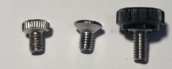
I really like the easy loading of a PCB, simply pull back the spring-loaded clip and drop the PCB in and release the spring. The thing that I disliked the most about this particular board holder was the knurled knob that secured the spring tensioner. The darn thing was so tiny I could not apply sufficient torque to actually tighten the screw in place. The above images show a replacement screw that I found with a hex head hole that I could use an Allen wrench to tighten, which was a huge step forward, but still somewhat concerning as it requires having the correct wrench nearby at all times.
So, I looked around for yet another solution, finally finding the right screw/knob on eBay.


The first screw in each image is the original screw, while the second is the hex head version and finally the third is the eBay find.
While the new holder was working well, there are certain situations that require tilting the board during assembly in order to get the best possible position for viewing and/or soldering.

Here, the USB connector pins are only partially visible, making it difficult see the pins during the soldering process. This got me thinking about building a tilt table that I could attach to the board holder, allowing me to position the PCB board during difficult soldering situations. Here are some images of the 3D designs of the parts for my tilting table.


The Top Plate (first image) attaches to the board holder two holes in the center of the plate. The two bosses on the bottom edge of the plate are a part of a hinge with the Bottom Plate, where a piece of 0.125" brass tubing will act as the pivot of the hinge (the two through holes are slightly larger than the 0.125" rod diameter for a loose fit). The two bosses in the center of the Top plate are attachment points for the two link pins that will allow various tilt levels by attaching to one of the several points in the Bottom Plate.
The Bottom Plate (second image), forms a hinge with the Top Plate, using the lower through hole (which is a tight fit to the 0.125" brass tubing). The seven holes at the top end of the plate are the various tilt points. The unit sits flat with the link rod detached from the bottom plate. Starting with the outer most holes the tilt angles are as follows: 7°, 18°, 25°, 31°, 35°, 39° and 42°.
The Link Rods (third image), are used to hold the tilt table into the desired angle. The pivot point and the angle select are sized for 4/40 screws. The pivot point uses nylon washers and nylock nuts to secure the link rods.


Here are some images of the completed assembly.

Here is an image of the board holder attached to the tilt plate, in the flat orientation. This is the normal position for soldering.


Here the tilt plate is set to the 35° position.
The resulting view under the microscope shows how this will be easier to solder.


Overall, I am very happy with the new board holder and the tilting plate. I can see this as another great upgrade to my soldering station.
Thanks for reading along!

Top Comments