


In my prior blog (Continuing to organize - laser marking upgrade to lightring. ), I had started to revive an older project with a few new features. I had originally built my light ring for my microscope (Nikon SMZ-2) back in 2012. This setup has been in almost constant use for the last 9 years. About 3 years ago, I had this idea to add a laser marking system to the light ring, so that I could simplify positioning my current work directly in the center of the microscopes field of view. I had printed a simple laser mount that could attach to the existing light ring to try out the concept. While everything worked, I wanted to tie the laser control into the existing light ring controller. The original light ring controller was based on an ATtiny45, in a 8-pin package. Unfortunately, all the pins on this device were full utilized. That and the fact that I had used a complex, and long since lost series of cables to reprogram this device, I abandoned this project.
My renewed interest in the project, kicked off by my desire to get a little bit more organized, caused me to revive this design. The first thing that I did was a complete update on the light ring controller. As DAB pointed out in one of the comments on the prior blog, that I had not described the actual light ring that the controller was commanding, I decided to write another blog filling in those details.
I guess I need to step backwards a bit and provide a bit of history on this whole project. When I first envisioned this project, in consisted of a pair of semi-circular PCBs that contained 6, three segment LEDs and a simple control pad (analog only) that provided a voltage indicating the state of four switches. One half of the ring assembly was a 'master', which would read the analog voltage of the switch array and take appropriate actions , and send commands via I2C to the 'slave' half of the ring. As the functions and patterns of the light ring got more and more complex, the ATtiny24's limited memory became an issue. Also, I wanted some LEDs on the controller keypad to help provide hints as to what mode the keypad was in. It was then that I decided to push all of the processing into a combined controller/keypad. With an intelligent controller attached, the two lines that had provided analog switch presses, were converted to a I2C bus, that could send LED settings to the two halves of the light ring.
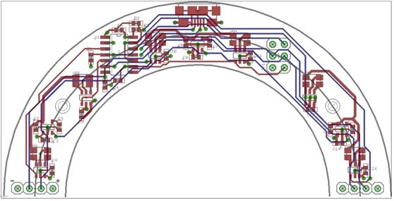
Here are the schematic and layout of the light ring boards:
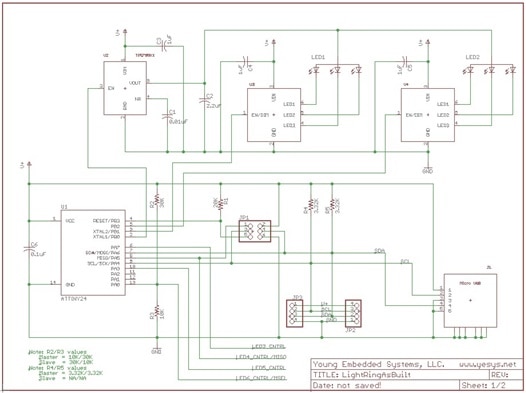
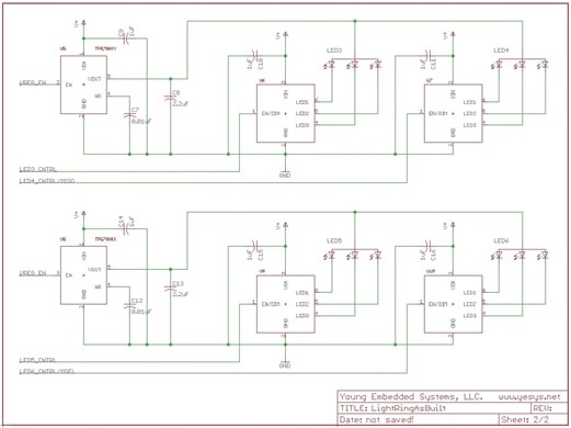
The Controller/Keypad connects to the 'master' light ring PCB via the micro USB connector (J1). This connection supplies power (+5 Volts) and a I2C bus to the light ring 'master' PCB. A legacy of the initial design is that the I2C pull-ups are located on the 'master' light ring PCB (R4 & R5). The I2C bus connects to the 'master' processor (ATtiny24) and to connectors (JP2 & JP3) which connects to the 'slave' PCB (along with +5 Volts and ground). The six LEDs are broken up into three groups of two LEDs each. Each group of LEDs has a regulator (4.2V) and dimmers for each of the LEDs. The dimmers are three channel, programmable constant current sources that are set by pulsing the EN/DIM line, each output on a chip is set to the same current level.
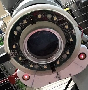
The LEDs are distributed throughout the ring, one LED approximately every 30 degrees. The two ring halves are connected together at both ends of the rings using a 4-pin header on side of the break with jumper plugs. Here is a picture of the assembled light ring attached to the microscope (shot from below the ring):
When I started this project, one of my goals was to be able to create different lighting patterns that could be used to increase the detail observable under my the microscope. In my early experience using this microscope for soldering, I noticed that the positioning of my illumination source (early on a simple halogen goose-neck lamp) made be differences in the image detail and quality. Sometimes the direct downward light washed out a lot of detail (like the markings on the chips), while a side angled light created shadows and made it difficult to see some of the pins on the chips. In addition to soldering, one of the uses of my microscope was viewing coins. In coins, where there are more textures, the side lighting did a great job of enhancing detail and/or scratches by creating shadows. From these observations, I knew that I wanted to be able to create several different lighting patterns and the ability to rotate these patterns through 360 degrees.
The light patterns that I chose to implement in my light ring are the following:
- All LEDs on - This is the simplest and most commonly used pattern. In this mode, there is no need to rotate the pattern, since all LEDs are on. The only control that is needed for this mode is adjustable intensity.
- Gradient mode - In this mode, starting at a point on the ring, intensities are set in and increasing value, up to a maximum (opposite of the starting point on the ring) and then in decreasing values back to the starting point. The intensity pattern, moving clockwise (in relative intensity levels) looks something like: 3, 4, 5, 6, 7, 8, 8, 7, 6, 5, 4, 3. The overall effect of this lighting mode is a bright to dim shift from one side of the ring to the other. This pattern is rotatable and variable in overall intensity.
- Three quarter illumination - In this mode, 9 of the 12 LEDs are turned on, with 3 of the LEDs turned off. This pattern is rotatable and variable in overall intensity.
- One half illumination - In this mode, 6 of the 12 LEDs are turned on, with 6 of the LEDs turned off. This pattern is rotatable and variable in overall intensity.
- One quarter illumination - In this mode, 3 of the 12 LEDs are turned on, with 9 of the LEDs turned off. This pattern is rotatable and variable in overall intensity.
- Single LED illumination - In this mode, 1 of the 12 LEDs are turned on, with 11 of the LEDs turned off. This pattern is rotatable and variable in overall intensity.
The dimmer ICs support 32 levels of illumination, but some of these levels are less distinguishable than others (especially on the higher end of the range), so I compressed the levels down to 16. Here is a graph of the weighting of the intensity levels:
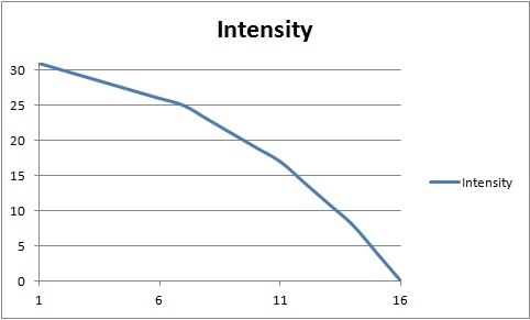
The dimming levels are effected by pulsing the EN/DIM line of the dimmers. Zero pulses commands the highest current/intensity (~25 mA to each LED segment in a package). These pulses are represented as the y-axis. The compressed intensity selection range is a value from 1 to 16 (0 is off) and is shown on the x-axis.
Here are a couple of videos showing some of the lighting effects (note - these images are shown from below the microscope/ light ring. The videos are shot with the exposures set very low):
In this video clip we start with the light ring in the 'All LEDs' mode. The mode is then changed from all to gradient and then through 3/4, 1/2, 1/4 and finally to the single LED mode. The single LED is then rotated through each position and then the intensity is step down and back up. Finally the mode is returned to the 'ALL LEDs' mode.
In this video clip we start with the light ring in the 'All LEDs' mode. The mode is then changed from all to gradient. The gradient pattern is then rotated through each position. Then the intensity is step down and pattern is rotated again. Finally the mode is returned to the 'ALL LEDs' mode.
Here are a couple of through the lens pictures to show the effect of rotating a '1/2 LEDs' mode pattern:
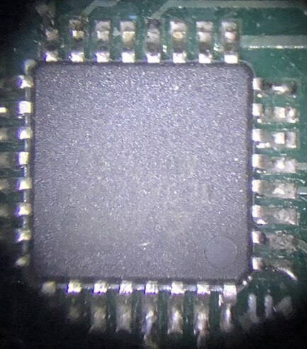
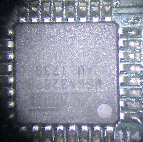
Both of these images are acquired at full intensity in the '1/2 LEDs mode). The only difference between the two images is a rotational change in the pattern of the LEDs.
I hope that this description sheds light (pun) on my project.
Thanks for reading along!
Gene
Top Comments