Since reading dougw post more than 2 years ( This Device Tickles My Fancy ) the TC1 component tester has been on my radar. Several times I have considered purchasing one, but somehow I never quite pulled the trigger on buying one. Recently, while going through my email inbox, I came across an ad for the DSO-TC2. This time I did not hesitate, but immediately added one of these to by shopping cart. Being the impulse shopper that I am, I also added a few other things that have been on my shopping list.
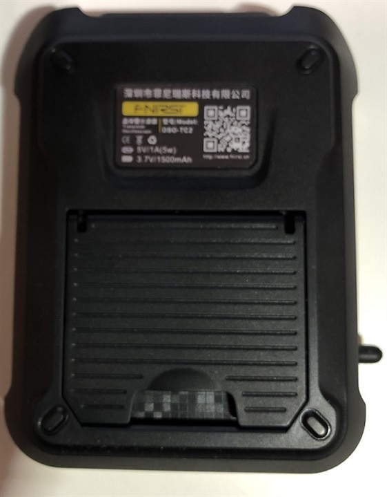
While not a huge purchase ($64.95), it is clearly a product has has a lot of potential. Also, with a very heavy background in component and board level test equipment development experience I just could pass this one up. The TC2 is a giant step up from the TC1, as this is a sleek and sexy design. The case is very well designed, robust and solid, while a pleasure to hold in your hand. The software interface is not as well designed, but still functional once you get familiar with the interface.

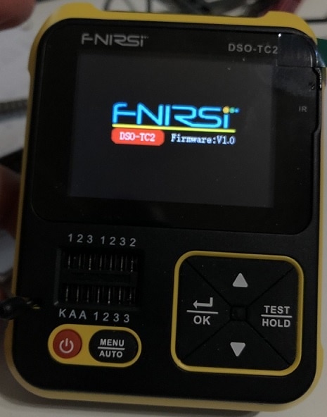
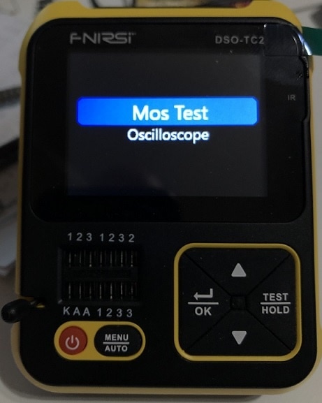
Powering up the device is pretty quick and the first image is a splash screen and firmware version image, soon replaced with a test/oscilloscope select screen.
As I was initially drawn to the component testing aspects of this product (I have other oscilloscopes to use) I decided to test out the performance of the component testing features. Not having a wide range of leaded components, my testing will be somewhat limited, but I am still interested to see how this little meter performs.
General notes and observations
In general, the meter measures components blindly, without out an knowledge of the device type or value. The component is simply placed into the zero insertion force connector such that it uses any of the sockets marked 1, 2 or 3 (they most not be the same number), and the Test/Hold button is pressed. Tests (extended testing) like: continuity, voltage, Zener diodes and some DS18B20 and DHT11 are reached through a menu (Menu/Auto button). I will go through the features that I was able to test in the following sections.
Resistance Testing
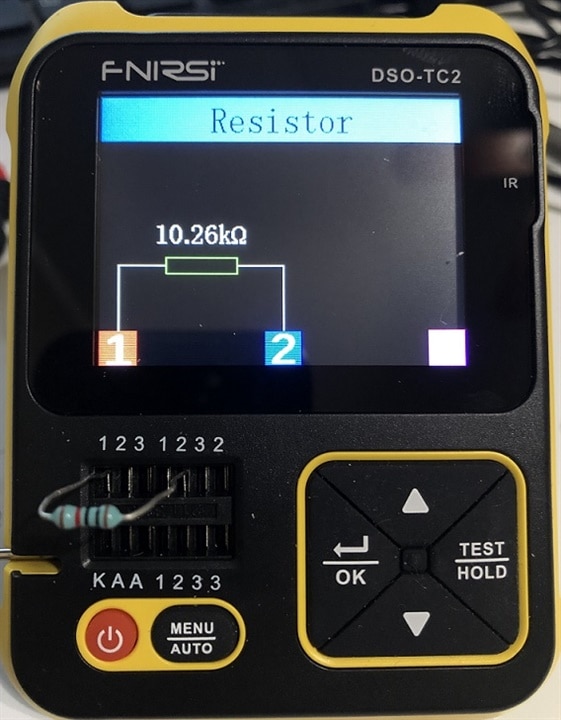
Using resistor values that I had on hand (mostly 1% metal film resistors), I tested a wide range of resistance values (10Ω to 1.4MΩ, across 24 values). Each resistor was measured 5 times on the TC2, averaged and compared to the listed values and those measured on my Multicomp-pro MP730027 DMM. Error values were computed for each resistance value, first against listed value and then against the measured value from the MP730027. Here are the results:
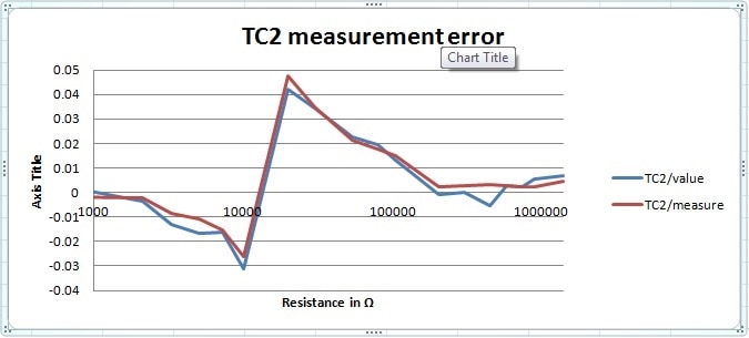
"TC2/value" is the error from the value of the resistor and "TC2/measure" is the error from the measured value of the resistor. Not too bad, less than 5% error across the board. With the largest error swing between the 10.2K and 20K resistors, I assume the meter made a scale change around that point.
Capacitance Testing
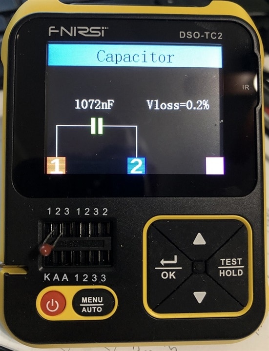
Using capacitor values that I had on hand (a mix different types), I tested a wide range of capacitance values (39pF to 10μF, across 20 values). Each capacitor was measured 5 times on the TC2, averaged and compared to the listed values and those measured on my Multicomp-pro MP730027 DMM. Error values were computed for each capacitancevalue, first against listed value and then against the measured value from the MP730027. Here are the results:
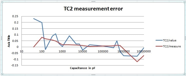
"TC2/value" is the error from the value of the capacitor and "TC2/measure" is the error from the measured value of the capacitor . There error here is quite a bit larger, especially under 100pF (close to the lower limit of 25pF) where the error is greater than 20%. Otherwise, less than 10% error across the board.
Inductance Testing
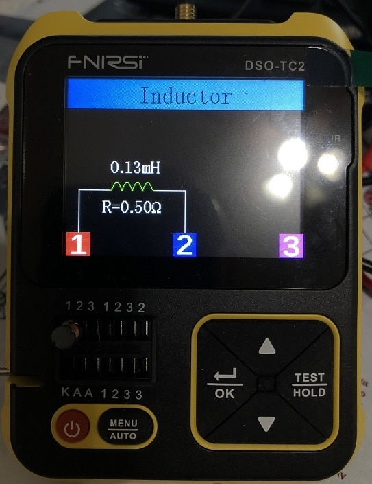
Using inductor values that I had on hand (a mix different types), I tested a wide range of Inductance values (15μH to 6.8mH, across 9 values). Each inductor was measured 5 times on the TC2, averaged and compared to the listed values and those measured on my Tenma 72-8155 LCR meter. Error values were computed for each Inductance value, first against listed value and then against the measured value from the Tenma 72-8155 LCR meter. Here are the results:
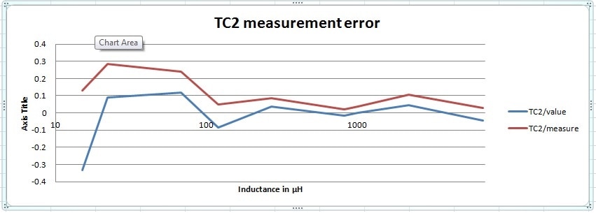
"TC2/value" is the error from the value of the inductor and "TC2/measure" is the error from the measured value of the inductor . There error here is quite a bit larger, especially under 100μH (close to the lower limit of 10μH) where the error is almost 30% (both meters struggled in this region). Otherwise, less than 10% error across the board.
Transistor Testing
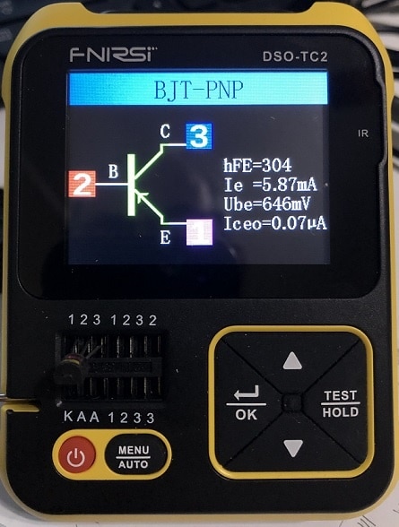
Using the only leaded transistors in my stock, 2N3094 and 2N3906, two transistors of each type were measured 10 times on the TC2 and the results (hFE, Ic and Vbe) were charted. I did not attempt to correlate the values as they are highly dependent the testing parameters (not controllable). Here are the results:
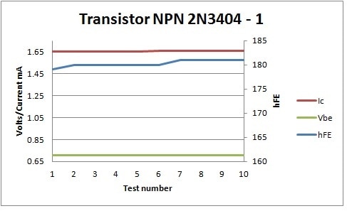
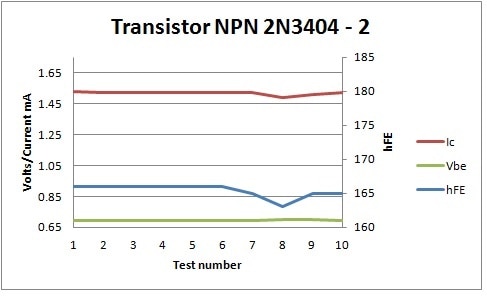
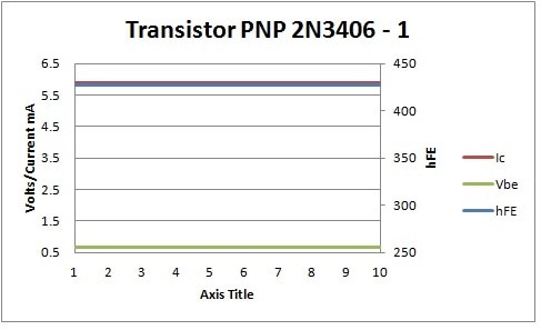

While charting the results, I used the same scaling on the axis as to better to compare the results. The test results varied, but in general the readings were fairly consistent.
MOSFET Testing
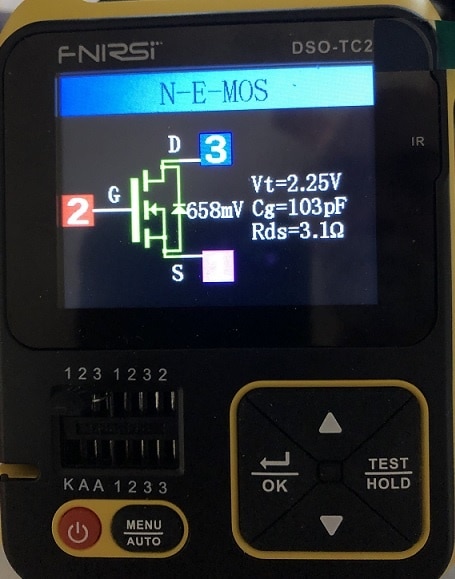

Using the only leaded MOSFETs in my stock, 2N7000 and BSS92, a single MOSFET of each type was measured 10 times on the TC2 and the results (Vt, Cg and Rds) were charted. I did not attempt to correlate the values as they are highly dependent the testing parameters (not controllable). Here are the results:
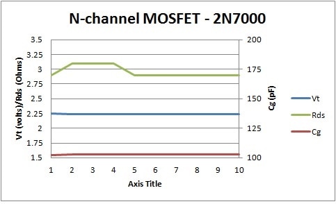
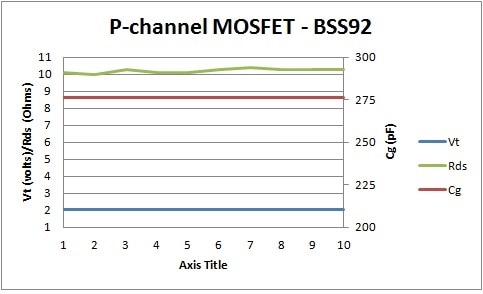
The repeatability of the results and the fact that they were somewhat indicative of the published specification for these devices some reassuring.
Diode Testing
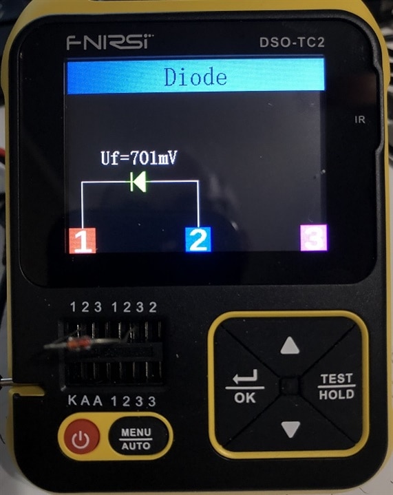
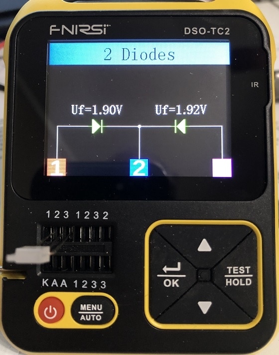
Using the limited number of leaded Diodes in my stock, I tested a standard silicon diode along with a 3-leaded, dual diode. Both items yielded expected results.
Other Tests and Messages
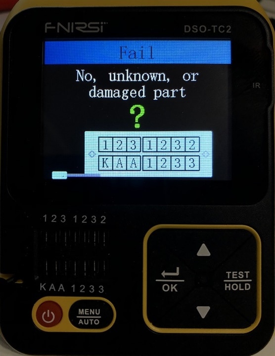
There are a few other screen messages that can occur in the component testing environment, naming the 'unknown or damaged part' message, along the IR Decoder results screen.
If there is no component inserted (or one outside the measurement capabilities/ranges) the following screen is shown:
The IR Decoding feature is available whenever the meter is waiting to test. An IR sensor is positioned along side of the LCD on the upper righthand side of the meter. When an IR signal is detected, the User Code and Data are displayed along with the waveforms (this capture was triggered by the remote for my TV).

Extended Testing Capabilities
Within the component testing environment, there is an extended menu which is available by pressing the MENU/AUTO button. This brings up a menu allowing you to select various test functions. Most of these tests are require higher voltages (like Zeners) or are functions that do not fit well with the auto discovery functions. Upon pressing the button you are presented with a setup/test menu.

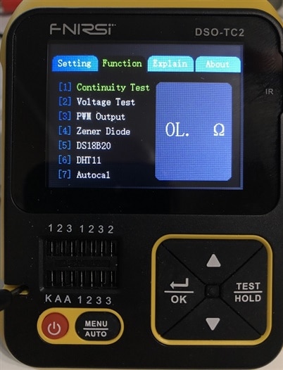
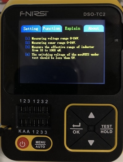
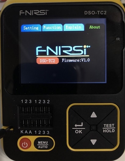
Using the TEST/HOLD button you can select the various tabs, showing the various menus. While on the 'Function' tab here are the available testing options:

Continuity Testing
In the continuity mode, the meter reads the resistance between the '1' and '2' contact points on the zero insertion force connector (It would have been nice if the twin alligator clips could have been used, with one of the inputs for this function). If the measured resistance is lower than a given value (seems to be lower than 1-2K Ohms), the value is constantly updated in the window. If the resistance is less than 20 Ohms (or so) the buzzer is turned on.
Voltage Testing

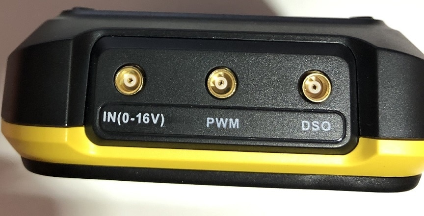
In the Voltage Test mode, the meter reads the voltage level from the MCX coaxial socket (labeled 'IN'), with the supplied twin alligator clips. This input is limited to 16 volts. To test this function I used my TACKLIFE MDC02 power supply to apply voltages to the TC2 meter, along with my Multicomp-pro MP730027 DMM. I stepped the voltage from 1 to 16 volts and collected readings from both the TC2 and MP730027. Error values were computed for each voltage level, first against the Power supply settings value and then against the measured value from the MP730027. Here are the results:

With the two error numbers tracking each other within 1%, I would say that the TC2 voltage error is less than 1%.
PWM Testing
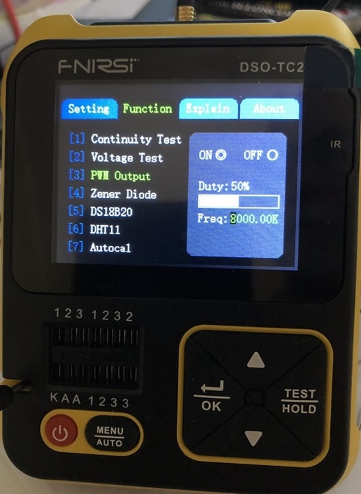
To test the PWM output waveforms, I connected the TC2 'PWM' Output to my Multicomp-pro MP730027 DMM and Tektronix TDS2014B oscilloscope (mostly used for verification and to view signal waveshape). I then tested waveforms from 1.5KHz to 8MHz, at different Duty Cycle settings. The output was relative clean and measurements confirmed that the signal output was accurate within 1% of the settings. (Note the MP730027 failed to read some outputs with very narrow pulse widths, like 1% duty cycle above 10KHz).
Zener Diode Testing
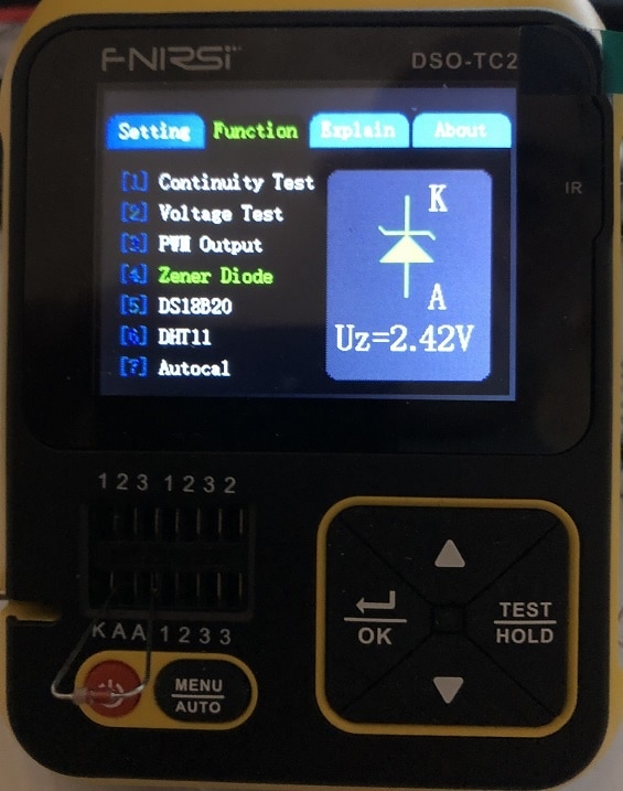

Using leaded Zener diodes that I had on hand, I tested a range of Zener values from 3.3V to 13V. While each Zener diode test reported a value lower than the specified voltage level, this is likely due to the selected current that the test was performed, but the results were close to the expected values. Here is a table of the results:
| Part number | Value | Measured Value |
| 1N746A | 3.3V | 2.42V |
| 1N749A | 4.3V | 3.48V |
| 1N741A | 5.1V | 4.93V |
| 1N751A | 5.1V | 5.00V |
| 1N5236B | 7.5V | 7.21V |
| 1N757A | 9.1V | 8.61V |
| 1N5243B | 13V | 12.7V |
Oscilloscope Testing

The Oscilloscope function of the TC2 is simple, but still but still very useful. The supplied probe has both 1X and 10X settings, covering a input range of either +/- 40V and +/- 400V. The voltage ranges are selectable from 10mV per division to 10V per division (Note: I was unable to set the 10X mode in the user interface, so if 10X is used, it appears that you need to apply math to the results). The display can include measurement values for Vmax, Vmin, Vaverage, Vrms, Vpkpk, frequency, period and duty cycle (these can be toggled on/off with a long press of the "TEST/HOLD" button).
Some of the trigger features are limited (Auto/Normal/Single), but that would be expected such an inexpensive Oscilloscope. With a sampling rate of 2.5MS/s and an analog bandwidth of 0 to 200kHz, this little oscilloscope still can manage to do lot work. The user interface is very clunky and it can take a while to switch between all of the adjustments, but still this is a very decent price to performance oscilloscope.
To test the oscilloscope feature, I applied a squarewave input, from 100Hz, to 200Khz and collected some screen images. As expected the squarewave got a lot less square as the input frequency was increased. Here are some screen captures:


Well enough for now. On the whole I feel as I really did get my money's worth with the TC2-DSO. This little meter can really do a lot and I feel that it will be a great addition to my workbench.
Thanks for reading along.
Gene

-

dougw
-
Cancel
-
Vote Up
0
Vote Down
-
-
Sign in to reply
-
More
-
Cancel
-

genebren
in reply to dougw
-
Cancel
-
Vote Up
0
Vote Down
-
-
Sign in to reply
-
More
-
Cancel
-

dougw
in reply to genebren
-
Cancel
-
Vote Up
0
Vote Down
-
-
Sign in to reply
-
More
-
Cancel
-

genebren
in reply to dougw
-
Cancel
-
Vote Up
0
Vote Down
-
-
Sign in to reply
-
More
-
Cancel
Comment-

genebren
in reply to dougw
-
Cancel
-
Vote Up
0
Vote Down
-
-
Sign in to reply
-
More
-
Cancel
Children