element14 Community
element14 Community
    Register Log In
  • Site
  • Search
  • Log In Register
  • Members
    Members
    • Benefits of Membership
    • Achievement Levels
    • Members Area
    • Personal Blogs
    • Feedback and Support
    • What's New on element14
  • Learn
    Learn
    • Learning Center
    • eBooks
    • STEM Academy
    • Webinars, Training and Events
    • Learning Groups
  • Technologies
    Technologies
    • 3D Printing
    • FPGA
    • Industrial Automation
    • Internet of Things
    • Power & Energy
    • Sensors
    • Technology Groups
  • Challenges & Projects
    Challenges & Projects
    • Design Challenges
    • element14 presents
    • Project14
    • Arduino Projects
    • Raspberry Pi Projects
    • Project Groups
  • Products
    Products
    • Arduino
    • Dev Tools
    • Manufacturers
    • Raspberry Pi
    • RoadTests & Reviews
    • Avnet Boards Community
    • Product Groups
  • Store
    Store
    • Visit Your Store
    • Choose Another Store
      • Europe
      •  Austria (German)
      •  Belgium (Dutch, French)
      •  Bulgaria (Bulgarian)
      •  Czech Republic (Czech)
      •  Denmark (Danish)
      •  Estonia (Estonian)
      •  Finland (Finnish)
      •  France (French)
      •  Germany (German)
      •  Hungary (Hungarian)
      •  Ireland
      •  Israel
      •  Italy (Italian)
      •  Latvia (Latvian)
      •  
      •  Lithuania (Lithuanian)
      •  Netherlands (Dutch)
      •  Norway (Norwegian)
      •  Poland (Polish)
      •  Portugal (Portuguese)
      •  Romania (Romanian)
      •  Russia (Russian)
      •  Slovakia (Slovak)
      •  Slovenia (Slovenian)
      •  Spain (Spanish)
      •  Sweden (Swedish)
      •  Switzerland(German, French)
      •  Turkey (Turkish)
      •  United Kingdom
      • Asia Pacific
      •  Australia
      •  China
      •  Hong Kong
      •  India
      •  Korea (Korean)
      •  Malaysia
      •  New Zealand
      •  Philippines
      •  Singapore
      •  Taiwan
      •  Thailand (Thai)
      • Americas
      •  Brazil (Portuguese)
      •  Canada
      •  Mexico (Spanish)
      •  United States
      Can't find the country/region you're looking for? Visit our export site or find a local distributor.
  • Translate
  • Profile
Restoration & Repair
  • Challenges & Projects
  • Project14
  • Restoration & Repair
  • More
  • Cancel
Restoration & Repair
Blog This Device Tickles My Fancy
  • Blog
  • Forum
  • Documents
  • Events
  • Members
  • Mentions
  • Sub-Groups
  • Tags
  • More
  • Cancel
  • New
Restoration & Repair requires membership for participation - click to join
Blog Post Actions
  • Subscribe by email
  • More
  • Cancel
  • Share
  • Subscribe by email
  • More
  • Cancel
Group Actions
  • Group RSS
  • More
  • Cancel
Engagement
  • Author Author: dougw
  • Date Created: 12 Apr 2020 6:10 AM Date Created
  • Views 1873 views
  • Likes 20 likes
  • Comments 7 comments
  • doug wong
  • diode tester
  • rlc meter
  • transistor tester
  • t7
  • restorerepairch
  • lcr meter
  • tc1
  • rcl meter
  • t7 multitester
Related
Recommended

This Device Tickles My Fancy

dougw
dougw
12 Apr 2020

Hello, my name is Doug and I'm a gadgetaholic, and the gadget in the 2nd picture below really tickles my fancy.

I have not been blogging much this year, but with all the lockdowns in place, I think it is important to stay connected, stay positive, communicate, find ways to relieve the stress, distract ourselves from obsessing over problems we can't solve, find ways to have some fun, maybe even find time to indulge in a few harmless vices.

This blog is about a quest I have been on for several decades. It starts back when I was a student …. my best summer job was in an electronics lab where I had all sorts of miscellaneous tasks that taught me a lot that I didn't know, and a lot that I would never learn in my engineering courses. One of the things I did was simply sorting components, which seems pretty menial, but I actually learned a lot from doing it, and it is why I can read colour code values at a glance without thinking or calculating. That lab had a General Radio LCR meter that I found intriguing and extremely useful for several of the tasks I had.

image

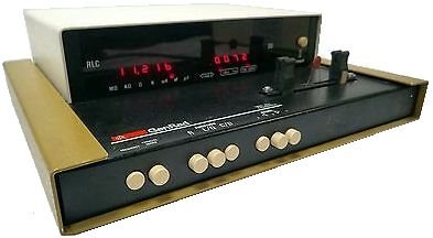
Ever since then I have had a disproportionately high desire (relative to actual need) to own a nice RLC meter, but they always seemed too expensive for me to justify purchasing. I still don't have a dedicated one like the GenRad, although I have collected a bunch of meters that more or less cover the functionality of an RLC meter.

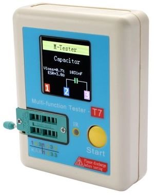
My latest instrument is a bit more of a novelty than a serious meter, but nonetheless it is very cool because it is deceptively smart and very versatile. I like having it more because it is cool than any high performance capability.

Here it is – the T7 Multitester. These instruments are quite fragile, both mechanically and electrically. This blog explains a few things I have done to improve the device and fix some of the issues.

image

Issues

  • The first issue is the USB charging port is recessed behind a thick plastic panel which barely allows the USB charging connector to make contact. It can make contact, but the connector falls out if you just look at it sideways. I designed a 3D printed replacement panel with a pocket around the USB port that allows the connector overmold to go into the panel far enough to properly seat the connector.
  • The second issue is that the device doesn't really turn off, it just goes into a sleep mode, so it continues to drain the battery when it is off.
  • A third issue that I've seen others have, is that the internal MCU can crash and there is no way to reset it.

Both of these issues can be solved by adding a power switch that disconnects the battery when the instrument is not in use. There is lots of room to add a switch to the top panel, so I designed a 2 part panel that locks the switch in place without any fasteners.

  • A fourth issue I discovered after taking the case apart is that the bosses for mounting the PCB do not extend all the way to the PCB, so if the screws are tightened, even minimally, the PCB will have to bend. I solved this by 3D printing some stand-off spacers and dowels.

In all, I used eleven 3D printed parts, a slide switch and some hookup wire to eliminate all the issues outlined above. However the parts are small so they print quickly.

You don't have permission to edit metadata of this video.
Edit media
x
image
Upload Preview
image

It still isn't a robust, high-accuracy instrument, but like I mentioned, something about it really tickles my fancy and I like it even more now that I have made some improvements.


Here are a few more examples of the T7 in action. This isn't any kind of exhaustive road test, I am not even showing all the functions it has, but I wanted to provide a little feel for how its operation compares to regular DVMs.

You don't have permission to edit metadata of this video.
Edit media
x
image
Upload Preview
image


I am pretty impressed that it can automagically figure out what random components and devices are plugged into it.

However, the quest continues to obtain a "real" RLC meter....


If you try these upgrades for your T7 using the enclosed 3D print files, you will need a standard slide switch with a body size (LxWxH) of 12.7 mm x 6.6 mm x 6.3 mm:

I think these would work:

E-Switch 500SSP1S2M2QEA 500SSP1S2M2QEA

E-Switch 500SP1S1M2QEA

Carling Tech 4M1-SSP1

C&K 1101M2S3CQE21101M2S3CQE2

C&K SP1101

The attached zip file includes .stl files for the 3D printed parts:

  • Spacer.stl - spacers for the PCB
  • DowelPin.stl - pins to hold the PCB to the spacers
  • SwitchPanel - panel to hold the slide switch
  • SwitchBezel.stl - exterior bezel for the slide switch panel


A multitester user manual can be found here:

https://www.circuitspecialists.com/content/430516/csi-tc1.pdf


Here is a schematic I found online here:

https://www.eevblog.com/forum/testgear/tc1-lcr-meter-transistor-tester-fix/?action=dlattach;attach=522938;image


The code also seems to available online.


I did a segment on a similar device earlier:

Sixth Sense - Interfaces - GraffitiBot blog 4

https://youtu.be/Bd36FYZKZqk

Attachments:
T7stlParts.zip
  • Sign in to reply

Top Comments

  • dougw
    dougw over 2 years ago in reply to genebren +4
    You are correct, the switch disconnects the battery, so it needs to be on to charge. I will attach the stl files in case anyone wants to try the same mods.
  • fmilburn
    fmilburn over 2 years ago +4
    Hi Doug, I really like your switch mounting design and friction pins to hold the board in place. Great way to minimize fasteners and make assembly quicker. I also learned something when you pointed out…
  • dougw
    dougw over 2 years ago in reply to fmilburn +4
    I made spacers for screws as well, but it only came with 1 screw, and I didn't have any more, so I opted for the dowels.
  • dougw
    dougw over 2 years ago in reply to jw0752

    These testers can do some unique things that are pretty useful. One of my associates at work today was faced with a perplexing situation where he could have used a diode tester that would show diode voltages above 4V. Unfortunately his Fluke couldn't do it and he didn't have one of these testers, so it took a little longer to figure things out.

    • Cancel
    • Vote Up +4 Vote Down
    • Sign in to reply
    • More
    • Cancel
  • fmilburn
    fmilburn over 2 years ago in reply to jw0752

    I have my M-Tester out today matching transistors for an experiment.  They are quite useful but I really should make a better enclosure for it.  AA batteries make sense too...

    • Cancel
    • Vote Up +4 Vote Down
    • Sign in to reply
    • More
    • Cancel
  • jw0752
    jw0752 over 2 years ago

    Hi Doug,


    I have several of these devices branded as M-Testers. I have purchased raw units for a few bucks from Banggood and put them in my own boxes. These were designed to run on a 9 volt battery but I wanted a longer use so for the two that I built my own cases I put AA batteries into the system. I have well over a year of use in both of the units and they still show 8.9V or more of battery voltage. On one unit I added wires and alligator clips as they are useful sometimes. I also moved the test socket off the board and onto the panel as I found that it was difficult to get the lock bard to work through the panel if it was mounted on the original board. The smaller one came with its own laser cut Plexiglas case and I had to stay with the original 9 volt battery. I have always found them accurate enough for my purposes and handy to help ID transistor leads and transistor types. The only problem I have had is that some of them were assembled with the socket lock bar closed. This causes the fingers to be held in a bad position by the solder. To fix this problem I had to open the lock bar and liquefy the solder long enough for the fingers to resume their proper position.


    image


    Thanks for your interesting post and modifications. It seems that I am not the only one who likes to modify commercial products to better suit ones preferences.


    John

    • Cancel
    • Vote Up +4 Vote Down
    • Sign in to reply
    • More
    • Cancel
  • dougw
    dougw over 2 years ago in reply to fmilburn

    I made spacers for screws as well, but it only came with 1 screw, and I didn't have any more, so I opted for the dowels.

    • Cancel
    • Vote Up +4 Vote Down
    • Sign in to reply
    • More
    • Cancel
  • fmilburn
    fmilburn over 2 years ago

    Hi Doug,


    I really like your switch mounting design and friction pins to hold the board in place.  Great way to minimize fasteners and make assembly quicker.  I also learned something when you pointed out that the back plate could be printed vertically with the switch holder stabilizing it upright - something I probably would have missed.

    • Cancel
    • Vote Up +4 Vote Down
    • Sign in to reply
    • More
    • Cancel
>
element14 Community

element14 is the first online community specifically for engineers. Connect with your peers and get expert answers to your questions.

  • Members
  • Learn
  • Technologies
  • Challenges & Projects
  • Products
  • Store
  • About Us
  • Feedback & Support
  • FAQs
  • Terms of Use
  • Privacy Policy
  • Legal and Copyright Notices
  • Sitemap
  • Cookies

An Avnet Company © 2023 Premier Farnell Limited. All Rights Reserved.

Premier Farnell Ltd, registered in England and Wales (no 00876412), registered office: Farnell House, Forge Lane, Leeds LS12 2NE.

ICP 备案号 10220084.

Follow element14

  • Facebook
  • Twitter
  • linkedin
  • YouTube