


Being the fortunate recipient of a 750W power supply, I thought it would be a shame if it were not given a chance to stretch its legs. It wasn’t originally part of my RoadTest proposal, but it seemed essential enough that I decided to spend just a little extra to make sure I could push the unit to its limits.
Testing a 750W Monster …
The headline figure for the QPX750SP is indeed its 750W power rating, but how can one actually test this? Ideally, this would be tested using a DC electronic load with an operating envelope wide enough to cover the full operating envelope of the QPX750SP but I’m not that fortunate to have one and my pockets aren’t nearly as deep either.
The next possibility is with a “make-do” approach. Unfortunately, living in a 230V-nominal country, mains appliances are mostly out of the question as even the maximum 2300W kettle would have a paltry 278W of load at 80V and I’d need three of them. I could try making my own load, but it’s not a simple task when that much power is involved – its stability and safety are primary concerns.
My original idea was to use some low-cost automotive inverters so I can use mains appliances as a load. Unfortunately for me, that idea was promptly put into disarray when the inverter I purchased with the intention of using it for this RoadTest arrived faulty and while I did eventually repair it, I wasn’t confident enough in its “500W” rating to actually put much load onto it. I put it in parallel with a two other 300W inverters, connected to some incandescent filament lamps, but then I realised that the “noisiness” of the inverters might actually affect the measurements and really limit this to being a “one-data-point” experiment. In the end, while it worked, this idea was scrapped …
I turned to element14’s shop for a quick fix in the form of the TE Connectivity/CGS TE750B1R0JTE750B1R0J 1Ω 750W-rated chassis-mount wire-wound resistor (Order Code 1760835). Luckily for me, it was in stock in an overseas warehouse, so it would arrive in just a week, but it would cost me AU$80 or so. I thought it was only fair that having been selected for the RoadTest that I go the extra mile. With its 1Ω nominal resistance, I would expect to run it at 27.386V at 27.386A, which should be on the envelope for the QPX750SP, while varying the voltage would allow me to sweep the load on the supply (at the cost of changing the operating voltage point). This is not ideal but with my Tektronix PA1000 Power Analyser, it would be possible to determine conversion efficiency, power dissipated and power factor of the QPX750SP.
Unboxing the #SpicyBar


Inspired by the #spicypillow hashtag of late, I think it’s only fair to call this one a #SpicyBar. It arrived in a yellowish cardboard box, lot number 20090455 dated Boxing Day (26th December) 2020. Someone must have been working extra hard! Inside, the resistor was packaged in Styrofoam to keep it safe, all the way from the UK warehouse.
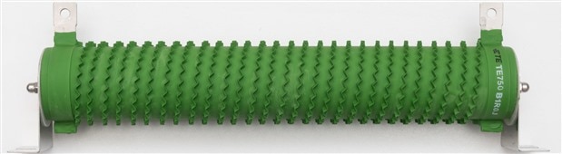
The unit consists of a corrugated band wound around a ceramic former and terminated to lugs at both ends. The whole assembly is coated in green Mullite for protection to maintain stability and longevity. The cylinder core is attached to mounting lugs which are designed to mount to a chassis.
I reused the crimped 6mm2 wire I had from the earlier MOSFET tests and bolted them to the lugs. To ensure safety, I decided to put the resistor on top of a terracotta tile to shield my furniture from the immense heat that it is likely to generate. With that, I wrote a script that would step the voltage up, millivolt-by-millivolt, recording the voltage and current delivered to the resistor (in two wire mode, as wire loss is counted as delivered power) and the power consumed by the power supply from the mains. The process took a while, and I watched on to ensure safety.
Radiant Results
Initial fooling about on the front panel seemed to reveal that the power supply was limiting itself into Constant Power (CP) mode despite not reaching 750W.

I was not expecting this, so I enquired with the manufacturer to find out what was happening, as I wasn’t getting more than about 707W. It was noted that the PowerFlex+ curve is only guaranteed at the points they have indicated and in-between these points, “up to” 750W is available, with no indication of how the interpolation between points is done.
While this explanation definitely makes sense, this was not my expectation based on their marketing material that said “limited by the power curve” on the front of the brochure, which had me thinking it would be able to deliver 750W as long as we don’t violate the maximum voltage and current capabilities. I guess this experiment was definitely important to learn something about the unit.
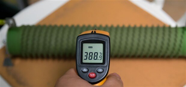
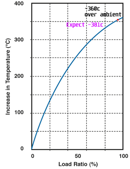
As the test continued, I heard a loud “clunk” from the gear. It turns out my terracotta tile had blistered underneath the resistor, perhaps because of trapped water or latent defects. It didn’t crack entirely, so I left the experiment to continue. In the end, the resistor surface seemed to look a bit more dull and brown due to surface emission, with a temperature almost 389°C. Checking with the datasheet, given the load, it was expected to be 360°C over ambient for about 381°C surface temperature. Given the measurement error of an uncalibrated infrared thermometer, I think this is a great confirmation of the power being dissipated.
During the process, the power supply seemed quite “chill” about the ordeal. The fans were slightly more audible, but not much worse than my desktop computer on a warm day. It didn’t sound particularly stressed, but then again, the QPX750SP’s idle fan noise is rather noticeable as it is.
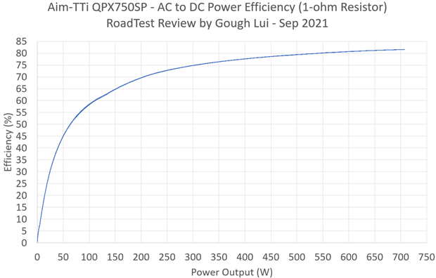
Computing the efficiency versus power delivered shows that with a 1Ω load, an efficiency of 50% or greater is only reached for loads of about 60W or more. An efficiency of 60% is reached by a load of about 110W; 70% for a load of 205W; 80% for a load of 550W. At maximum loading of 707W, the peak efficiency was about 81% which is not bad.
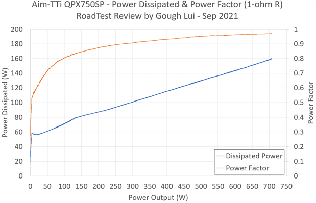
The acoustic behaviour of the QPX750SP can be explained quite easily by looking at the dissipated power curve. The power supply dissipates close to 60W even at light loads into the 1Ω resistor, likely because of the need to deliver lower voltages which come with an efficiency penalty. As the load increases, the dissipated load increases nearly linearly but at a limited pace, reaching a dissipation of 160W at 707W, or about the same as a mid-range desktop computer under load.
Power factor is not bad, eclipsing 0.5 almost immediately under load and staying above 0.8 for a load of 100W or greater. This is not unexpected for a high-power power supply, as this is necessary to ensure compliance with EU regulations and to ensure the limited power available from a single power outlet can be efficiently used. This power supply appears to employ active PFC which is noted in the Teardown chapter.
It should be noted that the efficiency profile will vary depending on the type of load as that will change the operating point. Changing the output voltage and current will yield different efficiency results – more details on this are given in the Instrument Performance Tests chapter.
Conclusion
It would be a shame if this power supply didn’t have a chance to demonstrate what it is capable of in terms of power delivery. To this end, I had planned to test it under full-load using automotive inverters running mains appliances, however, after receiving a faulty inverter and realising this would only result in a “single-point” result, I decided to try something different.
I spent about AU$80 on a TE Connectivity/CGS TE750B1R0JTE750B1R0J 1Ω 750W-rated chassis-mount wire-wound resistor (Order Code 1760835) from element14 that arrived within a week. Using this, I was expecting that it would be able to dissipate 750W by operating at 27.386V and 27.386A, hooked up with the 6mm2 wire from the previous MOSFET experiments and sat on a terracotta tile for protection against heat.
I discovered that the unit was only capable of putting 707W into the resistor due to a minor technicality regarding the PowerFlex+ curve. Contacting the manufacturer, I was informed that the power output is only guaranteed under the indicated points. The interpolation function between these points is not specified and power output is hence only “up to” 750W. This was a little misleading to me especially when the front page of the brochure says “limited by the power curve” which implied to me that it would be able to deliver 750W as long as maximum voltage and current limits are respected.
Regardless, the unit was capable of delivering 707W into the load and didn’t sound like it was breaking much of a sweat, only being subtly louder than when it was at idle. Efficiency into the load measured 50% by 60W; 60% by 110W; 70% by 205W; 80% for 550W and peaked at 81% for 707W which is not a bad performance. The active power factor correction of this unit also did a good job keeping the power factor above 0.5 almost immediately under any load, and above 0.8 for load above 100W.
It should be noted that these load and efficiency results are only valid for the condition for a 1Ω constant resistance – other loads result in different voltage and current operating points which would have different efficiency levels. This is explored in the later Instrument Performance Tests chapter.
---
This chapter is a part of the Aim-TTi QPX750SP 750W PowerFlex Programmable DC Power Supply RoadTest Review. More detailed chapters are linked from within the main review.

