


As a piece of bench-top test equipment, there’s a good chance that you might be using it “face-to-face”. I try to find out how easy is the BA6010 to use in this interactive scenario, what is it capable of and what are its limitations.
Documentation
In order to get the most out of your test equipment, I’m an advocate for reading the manual from cover to cover. Having done this for the B&K Precision BA6010, my impression of the supplied documentation is that it is a little too light on some details, with a number of inconsistencies in naming and formatting, and typographical errors as well. While most features are described in sufficient detail to get started, there are a number of errors within the “September 1, 2017” version of the manual that could be a little confusing at first. These including mislabelling of parts in the diagram, some headings being formatted as text, inconsistencies in the temperature range specification between the manual and datasheet and the use of incorrect accuracy values in the worked example on measurement accuracy just to name a few.
The section on measurement accuracy was probably the most difficult to understand, as the subscript terms were not intuitively defined within the derivation, resulting in some level of head scratching. For more information in regards to measurement accuracy, please see Chapter 6 where I’ve tried to make this easier with an Excel spreadsheet.
Face-to-Face with the BA6010
Testing of the BA6010 was done with the device running the supplied V.1.3.6 firmware. No firmware updates were available online at the time this review was conducted.
As battery analysers are not common pieces of equipment, readers can think of this battery analyser as a specialised type of LCR meter that has its output terminals configured for kelvin operation for optimising small-resistance measurement, in an isolated manner so that it can measure in the presence of DC voltages, with a fixed 1khz operation frequency and a limited resistance range up to 3.5kΩ; all mashed together with a voltmeter as well. The unit also behaves a little more like an LCR meter, providing other modes of measurement (other than R-V) so as to enable it to measure capacitances and inductances within a limited range of values.
LCD Display and Front Panel Navigation
The BA6010 is endowed with a rather attractive 4.3” 480x272 colour LCD screen with a matte anti-glare finish. Text is rendered clearly, in a large and bold easy-to-read font, making it a joy to use compared to some older segment-LCD or LED type displays. While the display is bright, perhaps a little too bright, the brightness is not adjustable.
Complementing this is the row of soft-buttons underneath the display which allow the user to select context-sensitive selections. A full numeric keypad is provided, with directional pad control and dedicated buttons to access settings/measurement/lock/print-screen and trigger features. The front panel also features LED indication for keypad lock and pass/fail status.
Accessing various features can involve pressing the SETUP button to access the settings menus, or DISP to return to the measurement screens. While not as intuitive as it could be, it’s easy to get used to and is quite similar to the interfaces seen on modern soft-button enabled LCD-based multimeters.
On the downside, the interface is slightly less user friendly than it could be, owing to the use of all capital letters throughout most of the interface, the use of non-standard abbreviations to conserve screen space and the general lack of use of colour with most of the interface being various shades of blue-green with white text overlaid.
Setup Menus
Device parameters are set through the setup menus, of which four are available by pressing the SETUP key followed by the corresponding soft-key underneath the display.
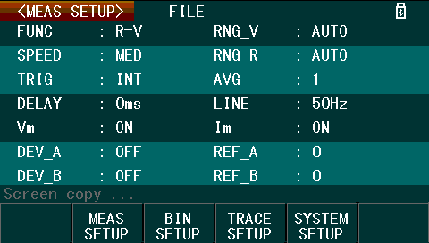
The default set-up screen is the Measurement setup menu. This is probably the most useful menu, as it allows for most of the measurement parameters to be configured, including the measurement function, speed, ranges, trigger sources, averaging, delay, line frequency, display of measurement parameters and deviation display. Using this menu is not always necessary – on the Measurement display, using the cursor keys and soft-keys allow the function, speed and ranges to be altered directly.
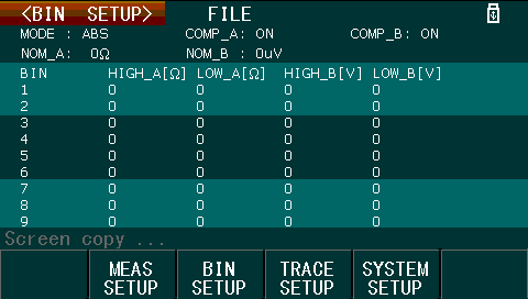
The Bin setup menu allows for the values for the binning feature to be configured. For more information on the Bin mode and display, please see Chapter 5 where it is discussed with the handler interface.
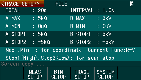
The Trace setup menu allows for configuration of the parameters used for the trace display mode. Unfortunately, it seems this mode is rather limited, requiring pre-configuration of the maximum and minimum values for each of the measured parameters and total record lengths/intervals prior to use. Redefining these values after a collection has started seems to reset the collected trace data. The trace mode also allows for configuration of value “boundaries” which will stop the trace scan feature.
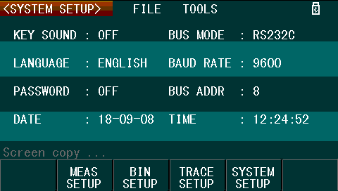
Finally, the System setup menu allows for the onboard beeper to be disabled, the language to be changed between Chinese and English, the setting of a password, date and time (kept by an internal RTC) and remote-control interface (of which only one can be used at a time). As this unit does not have GPIB fitted, selecting GPIB in the menu results in an error message stating it is not available.
Measurement Display
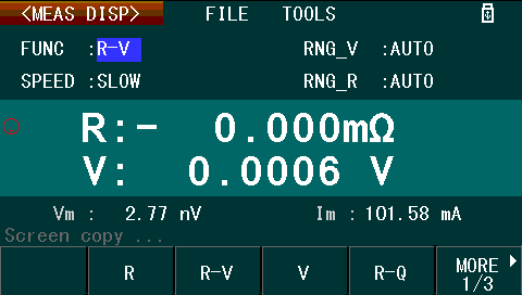
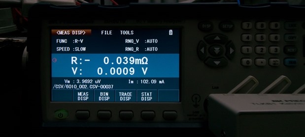
The measurement display is the main display you would use when interactively using the device. This mode resembles the display you might expect to see on a benchtop multimeter, showing the measurement parameters and measurement values.
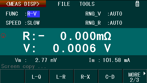
As noted earlier, it is possible to change some measurement parameters directly through using the cursor keys within the measurement display. For example, here, we are toggling through the three soft-menus of measurement modes available (in the bottom line).

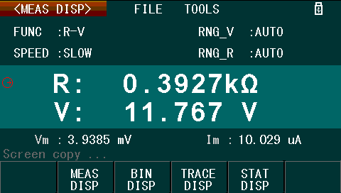
For example of a basic measurement, here is a basic resistance and voltage measurement of a completely sulfated sealed lead-acid battery.
Trace Display
The trace display allows for monitoring values as they change over time. Provided appropriate limits have been configured in the Trace setup menu, the scan can be started from the Trace display. A cursor and Max-Min data display are available.
Unfortunately, this mode is rather limited in its functionality as the horizontal scaling is fixed to a certain number of points across. For longer captures, to see all the data requires cursoring through the readings one value at a time using the navigational keys, which is quite slow. If the scale of the graph is not correctly set prior to starting the scan, then the plot will not be useful as changing the parameters post-capture seems to reset the plot.
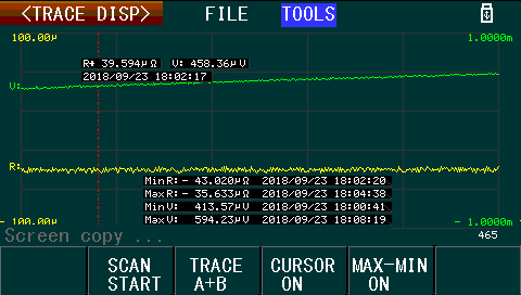
I have noticed that on very long traces, the screen does occasionally flicker some illegible text in the bottom left corner, which suggests some kind of possible firmware bug.
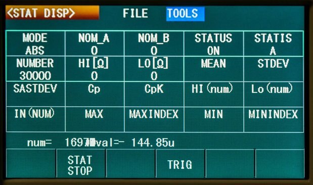
Statistics Display
The statistics mode deviates from the other modes in that the statistical parameters are set within the statistics display itself rather than through a dedicated settings page. Up to 30,000 readings can be used for the in-built statistical calculations, with the possibility for manual triggering. In my experience, while the mode did work and could be of use in standalone use, if a PC were available, directly analysing the raw data over the remote-control interfaces may prove more instructive.
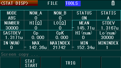
Like with the trace mode, it seems that long captures cause graphical glitches on the screen as well, suggesting the firmware lacks some polish.
Data Logging, Screenshots and Settings Save/Recall
The BA6010’s front panel USB host port allows for the use of USB flash memory for the exporting and saving of screenshots, CSV data logs and instrument settings. This is in addition to a limited amount of onboard instrument settings memory.
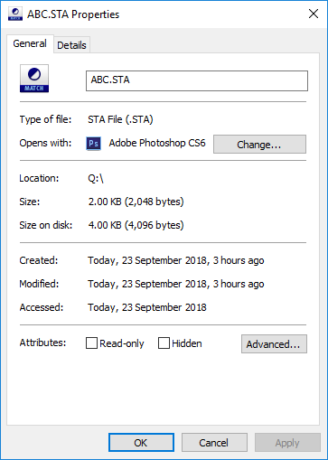
Instrument settings are saved as .STA files of 2048 bytes in length. This can be copied from the internal memory to the USB drive from the BA6010’s interface. Instrument settings can be restored through the interface and seem to consist of raw instrument binary configuration memory.
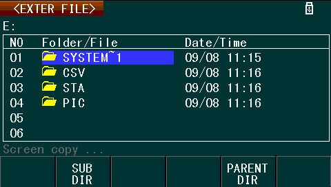
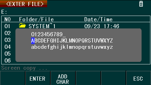
File locations and names can be chosen through the interface, however, using the on-screen keyboard can be somewhat frustrating due to its layout.
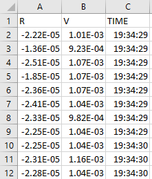
In measurement mode, measured data can be recorded to an automatically named .CSV file as well, displaying the name and sample number on-screen during recording.
It was observed, however, that on longer recordings that the unit would “pause” as data was flushed to USB resulting in gaps in the recorded samples. This limits the usefulness of this feature, especially at higher sample rates.
Screenshots can also be taken to external USB memory by the use of the “COPY” button on the front panel. This results in the screen being captured to a .GIF file, stored within the /PIC subdirectory of the USB drive. Unfortunately, each captured screenshot has the “Screen copy …” text obscuring any data present on the status line.
One limitation is that the BA6010 works with only FAT/FAT32 drives and cannot handle drives with too many files already stored on the drive. I have encountered situations where the drive “hung” the BA6010 during detection requiring a power cycle, so I recommend using a fresh small-capacity USB drive for dedicated use with the BA6010. I have also encountered situations where the first screenshot on a fresh USB drive was recorded as “zero bytes” despite showing that the screen copy had been completed and the analyser shut down using the front power button before removal. As a result, it might be a good idea to take “vital” screenshots twice.
Test Probes
The BA6010 includes a set of Kelvin clips for testing. The TLKB1 is designed for use with the BA6010 and its “block” assembly simplifies connection to the instrument, eliminating the possibility of incorrect connection. The clips themselves are gold plated with flexible contacts that have ribbed jaws. These clips form a good connection with battery terminals, holding securely and making a positive electrical contact.
Unfortunately, as the clips themselves are somewhat bulky, their suitability for testing cylindrical cells is rather limited. Whereas some other “field” based testers have pogo-pin style probes for use on flat cell contacts, this is not something the BA6010 includes. As a result, it’s probably a requirement that you customise the cell connections as necessary depending on your application, as the layout and geometry of the connections will impact on the measurements obtained.
The BA6010 also automatically detects anomalies with the Kelvin probe assembly, warning when any one of the four lines is unexpectedly open. This prevents false readings from being presented. In practice, this resulted in transient warnings as the probe clips were being connected or disconnected, confirming its functionality.
Measurement of low resistances requires more than just Kelvin connections, as there are also other sources of error such as thermal EMFs which can develop at the interface of dissimilar metals – an effect exploited by thermocouples. To ensure the highest measurement accuracy, the BA6010 is capable of nulling out the zero-resistance point by performing a calibration procedure with the clips shorted together.
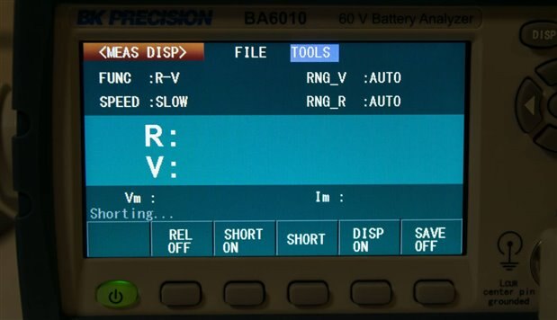
Rather humorously, this procedure is referred to as “Shorting …” by the analyser, but rest assured, nothing bad is happening. Although if you fail to arrange the clips to minimise their resistance for the shorting procedure, you may inadvertently introduce error into the measurement – so be sure to complete it as instructed after the instrument has warmed up and leave the “Short” compensation mode switched on for the highest accuracy.
Noise and Power
As the analyser itself does not dissipate significant power unlike a load tester, it’s generally very quiet. Aside from the keypad beeps which can be disabled, the only other major source of noise is the clicking of relays used to change measurement range. As a result, it’s quite welcome to stay on my bench.
The one concern I had was with regards to its 220V rating. It claims that the 220V rating is +/- 10% for an acceptable AC input range of 198-242V. As a person living within a “230V” harmonised country, that is actually running 240V, that can run up to 264V in extremes, I felt a little nervous about using the BA6010. Even during a normal day, I know my mains voltage reaches 245V on average. During many hours of use, I did not observe any failure or significantly unexpected behaviour from the BA6010. While being “out-of-spec” with regards to input voltage could theoretically reduce the instrument’s lifetime and affect its accuracy, in my RoadTest experience, it seems that this was not a problem.
Conclusion
The supplied documentation with the BA6010 leaves something to be desired, as it is rather light on details in some cases and in others, contains typographical errors, confusing explanations, incorrectly labelled diagrams, inconsistent formatting and other subtle errors. Despite this, the information supplied is sufficient to get started.
Using the BA6010 is no more difficult than using most modern LCD and soft-button enabled multimeters and its large, bright, 4.3” 480x272 colour LCD screen with matte anti-glare finish is a great asset. Menu navigation is done through a mixture of soft-buttons, dedicated buttons and a directional pad, which is relatively intuitive and easy to master. Readings are displayed in a crisp, easy-to-read font, at a large size. While the LCD screen is in colour, the interface only makes limited use of the colour capability with mostly solid colour regions on the screen and white text throughout. The use of all caps text through most of the interface, along with unusual abbreviations does make the interface a little less user friendly.
The unit offers an array of measurement modes which include R, R-V, V, R-Q, L-Q, L-R, R-X, C-D, Z-θd, Z-θr and R-C. In the measurement display, it behaves similar to a multimeter, displaying measurement values and measurement parameters. In the Bin mode, it categorises the tested sample based on the measured value. In the Trace mode, a rudimentary graph of the measurement can be built up over time. Finally, in the Statistics mode, statistics on a number of readings can be computed within the instrument.
In my experience, I spent most of my time operating within the Measurement mode where it performed as expected. The Trace mode seems to be a good use of the LCD screen capabilities of the unit, but unfortunately, its implementation is somewhat basic requiring scales to be pre-set prior to measurement with no option to rescale or auto-scale. The X-axis is also fixed in scale, resulting in tedious sample-by-sample cursoring to scroll the graph along. In both Trace and Statistics modes, with sufficient samples, the screen does display visual corruption in the status line, suggesting a lack of polish in the firmware.
Instrument settings can be saved to internal memory and the onboard USB host port allows for connection of external USB flash disks for transferring settings, storing settings, logging data to .CSV files and taking screenshot data. In my experience, .CSV logging exhibited periodic pauses in data collection while flushing data to disk and occasionally, zero-byte screenshots were experienced on freshly formatted USB devices. It is also noted in the manual that devices with too many files stored may not be used with the BA6010 – in my case, I observed the instrument locking up once the device was attached.
The supplied test probes are well designed, featuring flexible ribbed gold contacts which hold onto battery terminals while making solid contact. The pre-arranged connections allow for quick, error-free connections to the analyser, with the analyser’s inbuilt nulling features further improving measurement accuracy. The large size of the probes, however, make measurements on small cylindrical cells difficult – a set of pogo-pin style probes might be a better option, but it is likely that most users will need to develop a solution specific to their needs.
The BA6010 is quite welcome on my bench as it’s quiet - keypad beeps can be disabled, leaving just the clicking of relays used to change measurement range. The one concern I had was with regards to its 220V rating. Despite being in a “240V” country, during many hours of use, I did not observe any failure or significantly unexpected behaviour from the BA6010. While being “out-of-spec” with regards to input voltage could theoretically reduce the instrument’s lifetime and affect its accuracy, in my RoadTest experience, it seems that this was not a problem.
---
This blog is part of a series of posts for the B&K Precision BA6010 Battery Analyser RoadTest, where you will find all the links to the other parts of the review.
Top Comments