


Just over half a year ago, I was fortunate enough to be chosen as a reviewer of the Rohde & Schwarz HMP4040.04 384W Four-Channel Programmable Power Supply, which I reviewed here. The unit was a stellar performer, but unfortunately, it suffered substantial damage in transit. In fact, it seems all reviewers were unfortunate to have had some level of damage to their HMP4040 units. I dutifully co-operated with the carrier and lodged the necessary evidence and quote for repair, but I heard nothing back from them nor the management at element14 for over six months. As a result, I can only assume that whatever happened regarding the insurance claim, it may have been unsuccessful.
Initially the HMP4040 performed just fine, despite having a bent I/O plate and not sitting flat against the benchtop. But after a little testing, it lost the ability to run its fourth channel at all, and then the USB/LAN interface would be unresponsive on a cold start, requiring a power down and power-up in short succession to bring it back to life. It's still a sturdy performer in spite of this, but I thought I should deliver on my promise of a teardown and take the opportunity to try fixing some things while I'm at it. I was mainly preserving the unit and its packaging as evidence ... but I suppose that's no longer necessary.
In fact, it was partly because of the recent Infineon Truly-Differential Input MOSFET Driver RoadTest that I even bothered to try taking it apart - part of the reason was that it may have been made easier if I had a fourth channel.
Taking the Covers Off
In order to open up the power supply, I went by "feel" and tried to guess my way in. First step was to remove the HO732 I/O card by removing the two Philips screws and sliding the unit out. I gripped the bent backplate in a vise and managed to straighten it out slightly - so that was one easy fix. The next step was to remove the back panel by removing the six surrounding Torx screws. The back panel comes off revealing a solid thick steel chassis, but the lid still will not budge. Despite looking like it was made in halves, the top does not release.
I tried to remove the front panel and felt around - similarly there are six Torx screws but hidden underneath the front label. But they need not be removed! In fact, if you try to do it, you will (potentially) harm the front label and get nowhere fast. I tried ... well halfway before I realised the secret was the two screws underneath which hold the blue "shell" on. Once the two screws underneath are removed, the cover slides off to reveal a thing of beauty!
But before that - why was the unit wobbly on the bench? Well, unlike my expectations, the chassis was not bent. The internal chassis was straight as an arrow! What was bent was a slight "indentation" in the outer blue shell where the feet were mounted. Because of this, some creative work with clamps, pliers and vise grips quickly restored the shell back to straightness ... no more wobbling about on the table!
Onto the beauty that lies within -
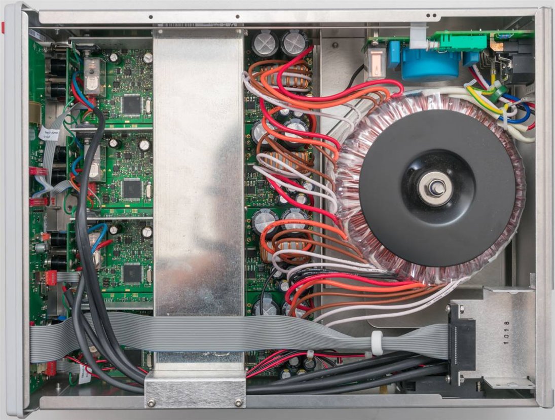
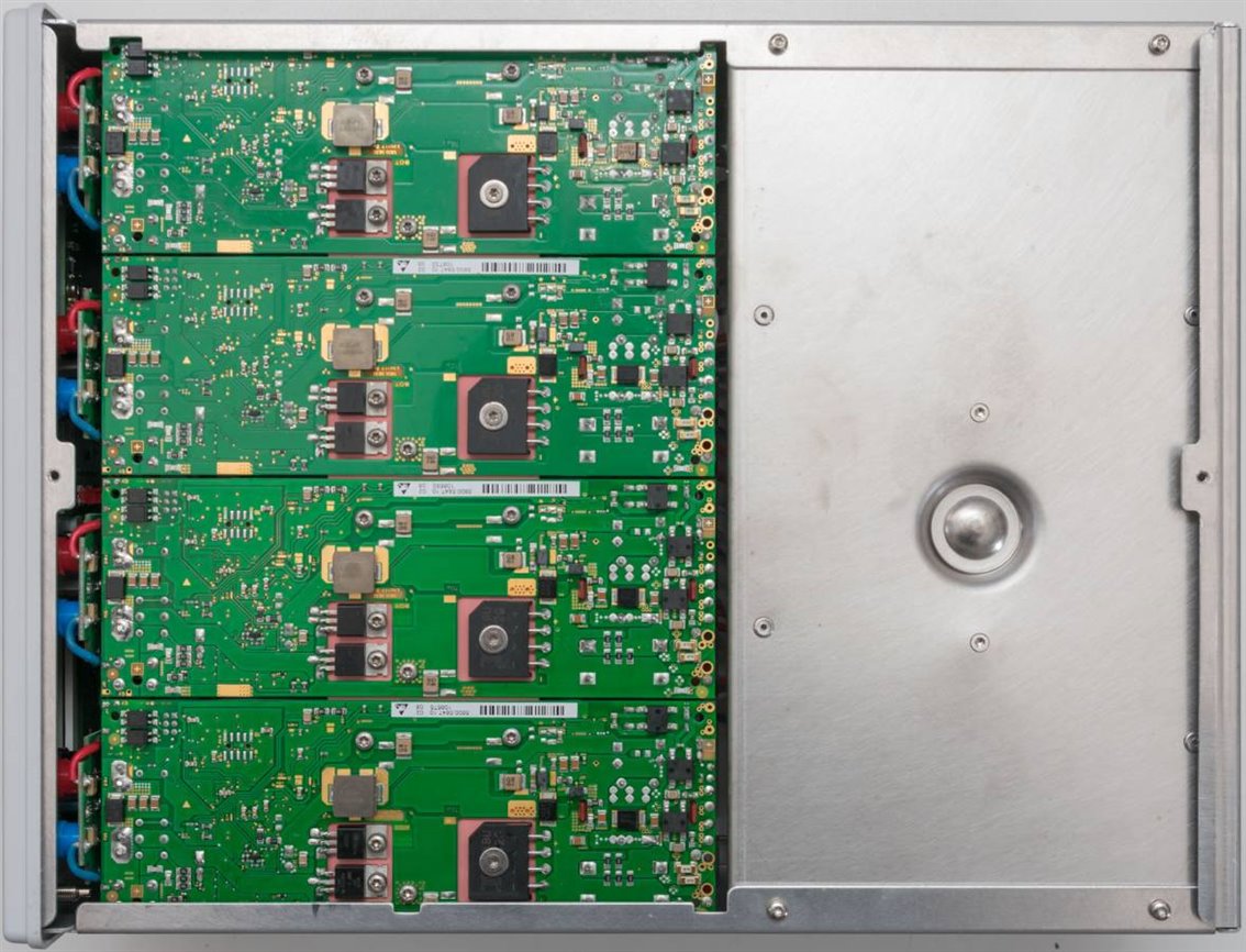
It's clear to see from the top view that there are four channels, each using their own independent but identical control boards. The output relays are visible as well, with the front panel sockets on their own PCB. The whole operation including the display is orchestrated by a PCB behind the front panel. The rear outputs are connected via sheathed cables to each of the channels. The rear I/O card cage is connected by a ribbon with ferrite suppressor, with a cable running from the front to the rear. A large toriodal transformer provides the power to all of the channels with six connections for each channel (presumably three windings each). This provides each channel with isolated power for the control circuitry as well, which is pretty interesting. The mains power control is housed on a separate PCB in the rear corner which has filtering components and perhaps the soft-start circuitry as well. The power button from the front actually pushes on a rod which pushes the switch on the rear board. Designed this way, there is a lot of safety and isolation.
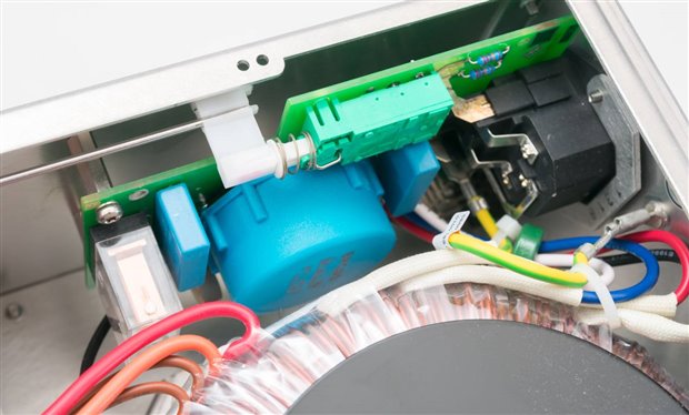
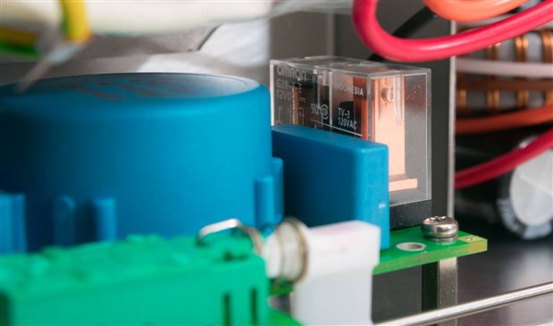
A closer look at the power control board appears to show a large EPCOS choke and an Omron relay, perhaps to short out the soft-start circuitry after a time delay. Already, we can see quality components in the unit, and there's plenty more of it to come.
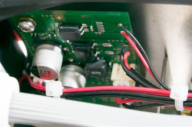
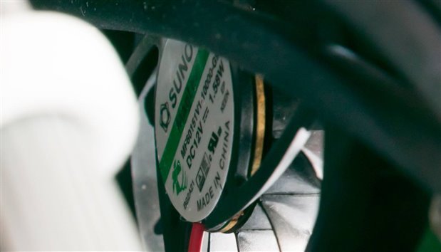
Tucked away on the side appears to be a fan control board of sorts. It even has solid capacitors and optoisolators which seems pretty fancy for some fan control. The fans themselves are Sunon Maglev series (MF60151V1-10000-G99) fans rated at 1.58W each.
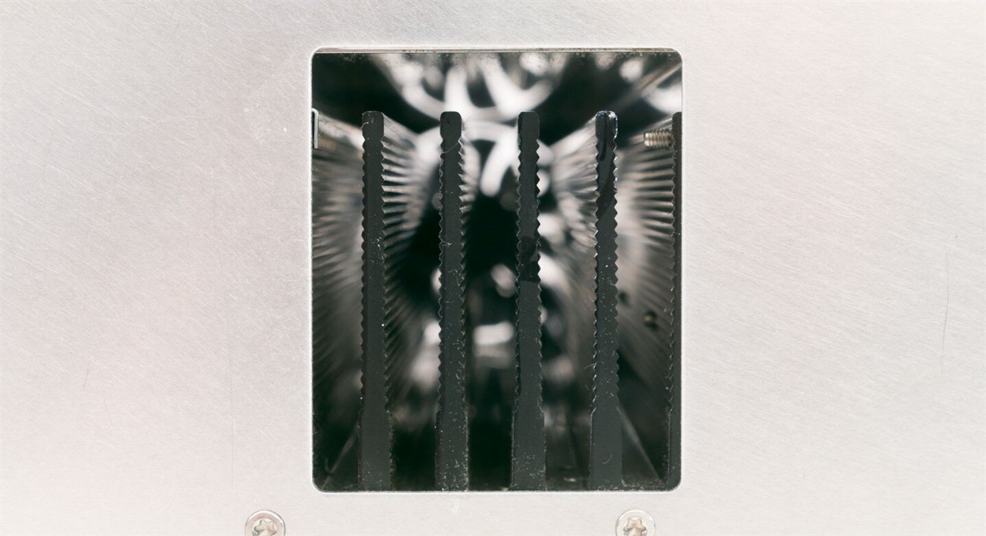
There are two fans in the HMP4040's design with a vent grille on the left. As it turns out, the rear fan cools the transformer and PCBs whereas the front fan is dedicated to drawing air past a long channel heatsink that runs across the full width of the power supply. Various power semis are mounted to this heatsink using sil-pads for insulation and thermal transfer, but this design seems rather cool (if you'd excuse the pun) as it means the heat is more effectively dealt with, without creating a lot of turbulence which would create audible noise.
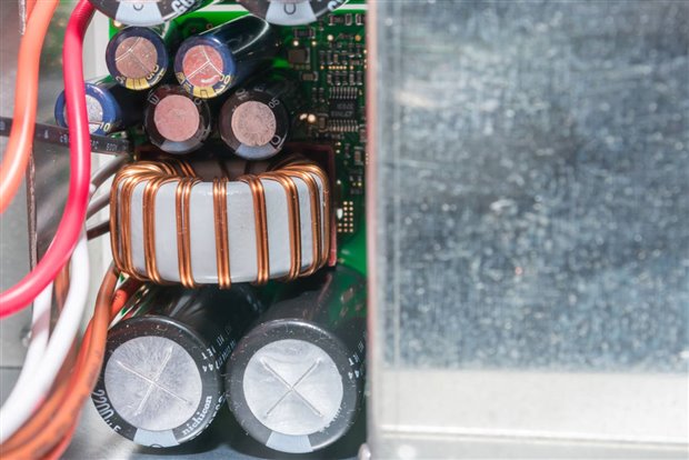
On the input side of each channel, we can see a mass of capacitance, along with a choke for filtering. That's great to see. But what's even better are the knowledge that these are high quality capacitors which are likely to stand the test of time - Nichicon and Panasonic (Matsushita) which are both Made in Japan are clearly visible. The one that's a little more mysterious is Frolyt - I've never seen them before, but they come from a long-standing and highly-reputable German manufacturer which also makes custom capacitors for special applications. Good to see they're supporting local industry in a way, but with a history like that, I'd have to say that I can trust in their motto "The source of true capacitance."
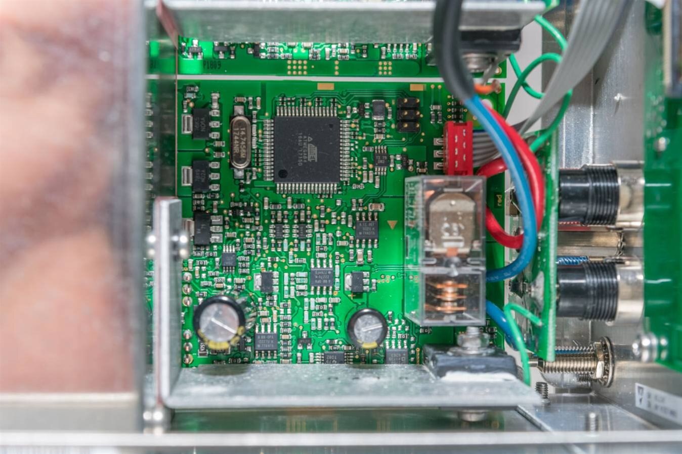
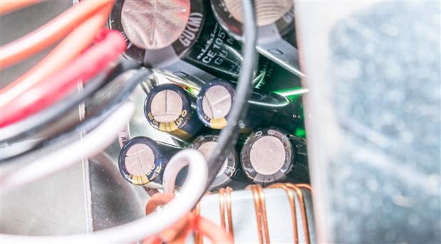
On the output side of the driver, we can see more Panasonic (Matsushita) capacitors, along with the OMRON relay responsible for output switching. Each of the channels is connected to the control plane via a ribbon with six staggered pins (in red). There also appears to be six pins connected to the ATMEGA64 8-bit AVR microcontroller with 64kB flash clocked at 14.7456MHz which may be used for programming (ICSP?). To put that into perspective, that's the power of about half of an Arduino Mega (original) board in one channel! Various Texas Instruments and Analog Devices opamps can be seen as well, along with a lone semiconductor package at the long end of an L-shaped heatsink, itself connected to the main extruded channel heatsink fins.
The underside of the unit is surprisingly clean, with the head of the bolt that secures the toroidal transformer visible to the right. There seems to be a slight indentation on the chassis, perhaps due to the mounting support for the transformer suffering some overstress due to the mishandling during shipping, but it appears to be minor. Nothing was rattling inside. Each of the four channel PCBs can be seen lined up on the side. A look at their undersides shows the design features a lot of attention to safety and reliability.
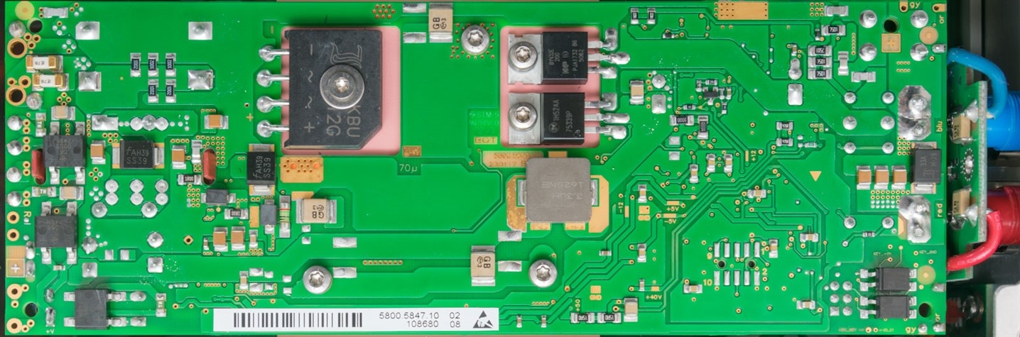
Each of the channels is controlled by this board, part number 5800.5847.10 with its own individual serial number. The various inputs from the transformer are soldered directly to the PCB on the left side, with the outputs on the right side. Notice that the board has an astounding number of SMD fuses (some resettable, others single-action) to protect it against catastrophic failure. From a quick look at the shot, I can count ten already. The board has slots cut-out with the main bridge rectifier and two semiconductors mounted through the holes into the extruded channel heatsink, isolated with sil-pads. Interestingly, there are three other bridge rectifiers on the left, as the supplies for the control logic and perhaps semiconductor drive rails are isolated as well. Towards the front, there appears to be two opto-isolators as well which seem to be connected to the six pins from the top, so perhaps there's more to the pins seen above. But the ten pads nearby are perhaps used for manufacturing purposes. A few of the tracks are labelled as test-points with the solder-mask cleared to form text in a nice premium ENIG (gold) finish.
The HMP4040 power supply really shows a premium design, executed with premium components with attention to safety and performance. I've rarely had the chance to tear apart something as well made - this is engineering porn.
Where's my Fourth Channel?
While the bent backplate, out-of-position shell and wobbly feet were an easy fix, the more intriguing question I had was why the fourth channel was inoperative. As all channels are identical, it was easy to do a bit of probing to see what was going on. Unfortunately, since there is no silkscreening or schematics available, this will be mostly a game of "spot the difference".
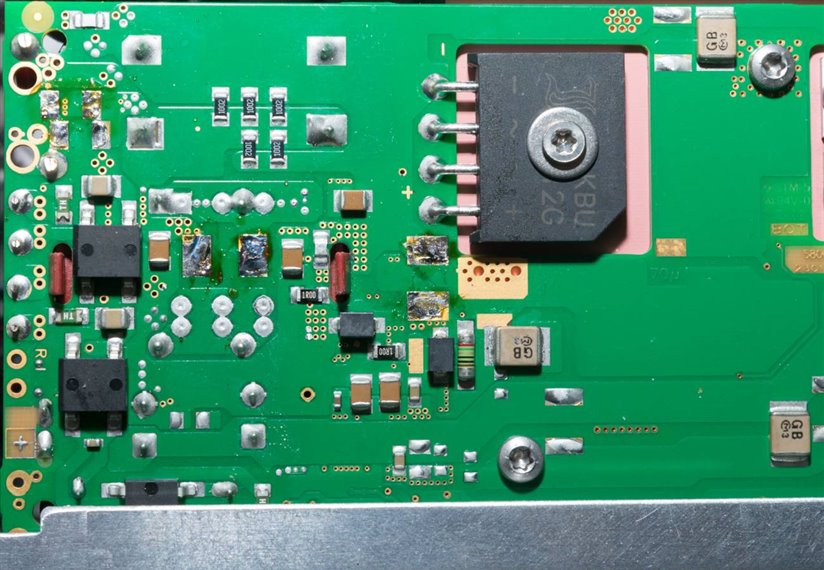
Starting at the input, I could already see something was wrong. The power supply for the main power stage goes through a pair of Littelfuse Nano2 fuses rated at 7A in parallel. In the case of the bad channel, both of these fuses (of course) measured open. A novice may just decide to replace these ... but of course, something had to have happened to cause them to blow. I was originally suspecting something simple like transit damage, but it seems the issue is perhaps a little more involved.
I then looked around for components which could have gone bad. I tested all the bridges in circuit - all were fine. Then, the SS39 90V Schottky diodes were tested only to find they were dead short - well this certainly wouldn't have helped. That alone could have probably caused the fuse to blow.
I quickly got out the braid and soldering iron and took those components off. I even put in an order to element14 (in my enthusiasm). But then, I got to thinking ... something else might be the cause. Best to check down into the output side of the unit to see what's going on.
Looking at the output, it seems the Schottky diode at the output was fine. The capacitors nearest the output measured identically in-circuit to the others. But then, I found the capacitors near the On Semiconductor HUF75339P MOSFET seemed to measure a dead short. I couldn't get a capacitance reading from the meter despite trying numerous times - it seems the solder they use forms an oxide coating thus it takes some scratching of the probes to get a good contact. I measured the FET in place and it didn't seem to be leaking in any way - so I presumed it was fine. Perhaps an overvoltage or reverse polarity event may have hurt the ceramic capacitor or electrolytic capacitor next to it? I then get out my tools again and desolder both, but both capacitors test just fine and the short still remains.
Then, I thought I'd have to remove more components to isolate the issue, so the 100 ohm SMD resistor connecting that "area" of the board was removed to "island" that part of the circuit. Hmm. Short still seemingly remains.
At this point, my suspect is a little transistor that is hidden just behind the electrolytic cap on the top side of the board. But to get to this will require removing all the semiconductors from their heatsinks to get the module out. At this point, my risk-versus-reward instinct kicked in and I chose to stop here. Why risk three working channels to save one that wasn't? As I only removed components which were not in the functioning chain of devices, I decided to shove them all into a zip-lock bag and reassemble the supply as is. The supply continues to work as it did before - sans the fourth channel, with no changes in its behaviour. But I suppose the easiest fix would be to get another channel module and solder it in - the problem being that these modules aren't sold as spares ...
Unfortunately for element14, I had to ring them up bright and early this morning to cancel the order ... success, unfortunately, was not on the cards. The cause of failure is still not conclusively determined - perhaps I was just unlucky with a one-off failure. But whatever the case is - it failed in a way that still allowed the rest of the unit to operate in a safe manner and that's not something that happens often in many designs.
---
This is a bonus posting - for the full RoadTest, visit R&S 4-Output Bench Power Supply, Prog (HMP4040.04) - Review
Top Comments