element14 Community
element14 Community
    Register Log In
  • Site
  • Search
  • Log In Register
  • About Us
  • Community Hub
    Community Hub
    • What's New on element14
    • Feedback and Support
    • Benefits of Membership
    • Personal Blogs
    • Members Area
    • Achievement Levels
  • Learn
    Learn
    • Ask an Expert
    • eBooks
    • element14 presents
    • Learning Center
    • Tech Spotlight
    • STEM Academy
    • Webinars, Training and Events
    • Learning Groups
  • Technologies
    Technologies
    • 3D Printing
    • FPGA
    • Industrial Automation
    • Internet of Things
    • Power & Energy
    • Sensors
    • Technology Groups
  • Challenges & Projects
    Challenges & Projects
    • Design Challenges
    • element14 presents Projects
    • Project14
    • Arduino Projects
    • Raspberry Pi Projects
    • Project Groups
  • Products
    Products
    • Arduino
    • Avnet Boards Community
    • Dev Tools
    • Manufacturers
    • Multicomp Pro
    • Product Groups
    • Raspberry Pi
    • RoadTests & Reviews
  • Store
    Store
    • Visit Your Store
    • Choose another store...
      • Europe
      •  Austria (German)
      •  Belgium (Dutch, French)
      •  Bulgaria (Bulgarian)
      •  Czech Republic (Czech)
      •  Denmark (Danish)
      •  Estonia (Estonian)
      •  Finland (Finnish)
      •  France (French)
      •  Germany (German)
      •  Hungary (Hungarian)
      •  Ireland
      •  Israel
      •  Italy (Italian)
      •  Latvia (Latvian)
      •  
      •  Lithuania (Lithuanian)
      •  Netherlands (Dutch)
      •  Norway (Norwegian)
      •  Poland (Polish)
      •  Portugal (Portuguese)
      •  Romania (Romanian)
      •  Russia (Russian)
      •  Slovakia (Slovak)
      •  Slovenia (Slovenian)
      •  Spain (Spanish)
      •  Sweden (Swedish)
      •  Switzerland(German, French)
      •  Turkey (Turkish)
      •  United Kingdom
      • Asia Pacific
      •  Australia
      •  China
      •  Hong Kong
      •  India
      •  Korea (Korean)
      •  Malaysia
      •  New Zealand
      •  Philippines
      •  Singapore
      •  Taiwan
      •  Thailand (Thai)
      • Americas
      •  Brazil (Portuguese)
      •  Canada
      •  Mexico (Spanish)
      •  United States
      Can't find the country/region you're looking for? Visit our export site or find a local distributor.
  • Translate
  • Profile
  • Settings
Personal Blogs
  • Community Hub
  • More
Personal Blogs
Hardware PI RACK
  • Blog
  • Documents
  • Mentions
  • Sub-Groups
  • Tags
  • More
  • Cancel
  • New
  • Share
  • More
  • Cancel
Group Actions
  • Group RSS
  • More
  • Cancel
Engagement
  • Author Author: mcb1
  • Date Created: 5 Aug 2013 11:59 AM Date Created
  • Views 3587 views
  • Likes 5 likes
  • Comments 12 comments
  • pi-face
  • piface_digital
  • pi
  • raspberryp-pi
  • rack
  • temperature_measurement
  • pirack
  • piface
Related
Recommended

PI RACK

mcb1
mcb1
5 Aug 2013

I was fortunate to get my hands on an early release of the PiFace PiRack. (I prefer to use the small i in the blog)


This has been mentioned in the PiFace documentation, but there was little other information.


The PiRack is designed to extend the GPIO pins of the RPi (Raspberry Pi) out to a series of right angle headers, and an end connector.

You then stack 4 x PiFace Digital boards (or any other boards) onto the connectors.

A second PiRack fitted to the last connector gives the option of seven boards.

As the video explains, 7 boards gives 56 Inputs and 56 Outputs.

http://www.element14.com/community/videos/9290


To overcome the supply issues, the designer ( Dr Andrew Robinson )has fitted a DC jack to provide external power.

He also fitted jumpers to select the 5v source (external or from Pi) and allow the select lines to be jumpered to avoid two boards having the same address.


image

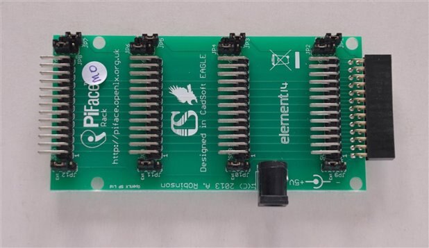
Photo from above the basic unit. Right side plugs into the Pi, while the left end is available for connections or another PiRack.


image

Bottom


image

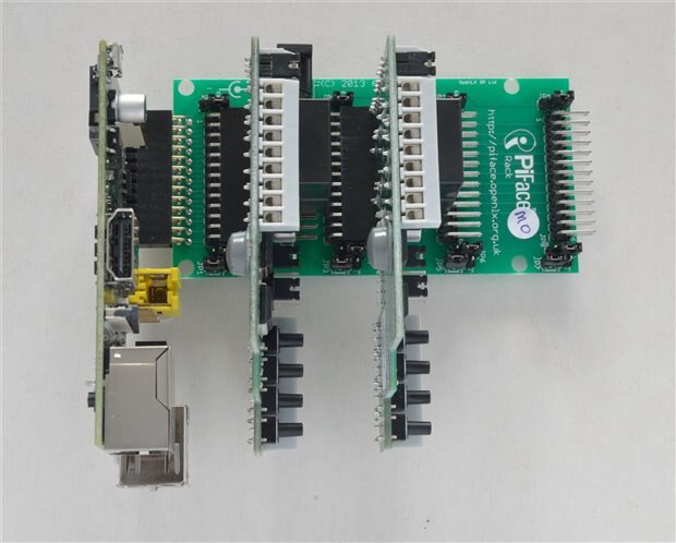
Photo of two PiFace Digitals fitted showing the clearance from the Pi, which allows the camera and other cables to be fitted.


image

Side view

image

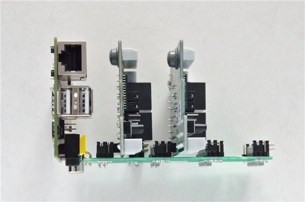
End view showing Input cabling distance from baseline. Consideration when mounting should factor in cabling.


image


image


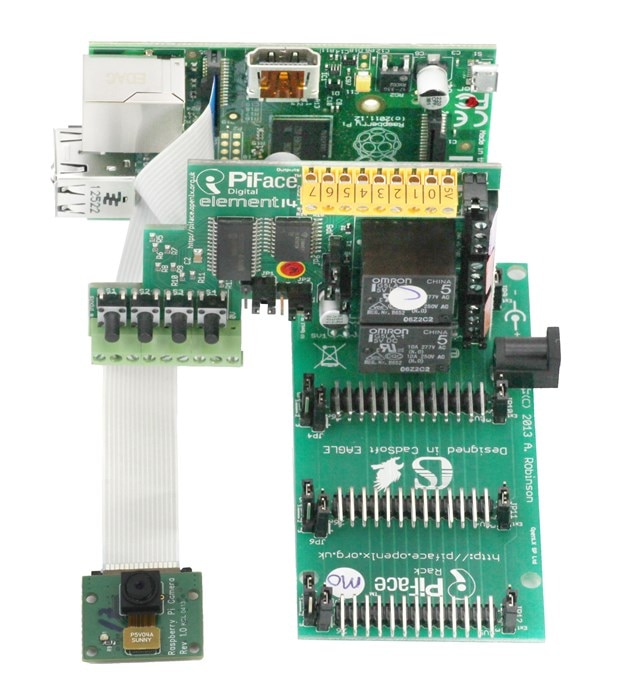
Two official photos showing the RPi with camera and PiFace Digital attached using the PiRack


Mounting

There are 4 mounting holes provided to secure the unit, however clearance for the Input cabling should be considered, as the photo above shows.

I'm not sure about permanently mounting the RPi or the PiFace Digital without some additional support that holds the boards at the correct spacing.

It is not good practice to use the connector as a sole means of support, as any flexing/movement is transferred back and results in the solder joint cracking.


Pricing

The NZ pricing is $14.95 (plus GST = NZ$17.20) which is very good compared to the other solutions.

The part code is 2327992 (UK price is £6.99) (Newark is 97W2503 $10.70) (CPC is SC13195 £8.39)


Documentation

The official release note is here Press release

Safety and Jumper info is here Safety leaflet


Uses

The RPi comes with a GPIO that allows many other items to be connected, and unfortunately the PiFace Digital removed that while only using a few itself.

If you wanted to connect a temperature sensor that controlled one or more outputs, then you were out of luck, unless you fit two rows of connectors (see PiFace Digital )


Some items require power as well as the data pins (ie I2C LCD), so multiple devices can require some creative wiring in order to satisfy the hardware needs.

If you are still in the test or prototype phase this can be a hinderance or worse an accident that renders one or more parts to the scrap heap.


Using the PiRack gives 5 sets of the GPIO pins, and the option to power with an external 5v supply.

This would suit anyone contemplating servo control, as these generally cause issues with spikes on the 5v line.


As these come into use, I'm sure we will see some more creative uses that may or may not have been considered when first designed.


In the meantime, get your orders in as I suspect these will fly off the shelf, while I write a review for "The Shed" magazine


Mark Beckett

  • Sign in to reply

Top Comments

  • jamodio
    jamodio over 12 years ago +1
    You should widen the pcb traces carrying power, they are too thin to reliably work as a power bus. My .02 Jorge
  • shabaz
    shabaz over 12 years ago +1
    I suppose in theory this could be sliced if people want (say) just a couple of slots. EDIT: removed my comment about two RPIs - just realized why that isn't possible!
  • mcb1
    mcb1 over 12 years ago in reply to jamodio +1
    Personally I think you are right. I would also have added some 0.1uF caps to ensure that 5v noise wasn't propogated. You could argue the supply does that, but its at the end of a long lead. It could also…
  • Problemchild
    Problemchild over 10 years ago in reply to mcb1

    I'm still waiting for mine like 2 years latter or something ....I bought my own and reviewed it on my Blog as well image

    • Cancel
    • Vote Up 0 Vote Down
    • Sign in to reply
    • More
    • Cancel
  • mcb1
    mcb1 over 10 years ago in reply to Problemchild

    Thanks

    It arrived totally out of the blue and with an embargo on info.


    It's a clever idea and hopefully there is a B+ version which addresses some for the power concerns made.


    Mark

    • Cancel
    • Vote Up 0 Vote Down
    • Sign in to reply
    • More
    • Cancel
  • Problemchild
    Problemchild over 10 years ago

    Nice Project there Mark amazed how I missed it it before...Almost a pimp my pi  article image

    • Cancel
    • Vote Up 0 Vote Down
    • Sign in to reply
    • More
    • Cancel
  • wymand
    wymand over 11 years ago

    I have a working Chicken Coop controller using the PiRack to stack boards.  Since the entire project uses a large number of 5V devices

    I use a single 5V supply and the 5V for the RPi is supplied by taking the top jumper of the Pi Rack and tying the three pins together and

    running 5V to that.  It has been working fine for months now.

    • Cancel
    • Vote Up 0 Vote Down
    • Sign in to reply
    • More
    • Cancel
  • wymand
    wymand over 11 years ago in reply to mcb1

    On page 7 of the PiFace manual it says it can either take power from or supply power to the Raspberry Pi 5V pin or can use an independent supply

    • Cancel
    • Vote Up 0 Vote Down
    • Sign in to reply
    • More
    • Cancel
>
element14 Community

element14 is the first online community specifically for engineers. Connect with your peers and get expert answers to your questions.

  • Members
  • Learn
  • Technologies
  • Challenges & Projects
  • Products
  • Store
  • About Us
  • Feedback & Support
  • FAQs
  • Terms of Use
  • Privacy Policy
  • Legal and Copyright Notices
  • Sitemap
  • Cookies

An Avnet Company © 2025 Premier Farnell Limited. All Rights Reserved.

Premier Farnell Ltd, registered in England and Wales (no 00876412), registered office: Farnell House, Forge Lane, Leeds LS12 2NE.

ICP 备案号 10220084.

Follow element14

  • X
  • Facebook
  • linkedin
  • YouTube