


My electronics skills get called upon for all sorts of things.
What
Some years ago a close friend asked if I could help with some LED tailights he was fitting to his Hotrod.
He had purchased some american made units that had allowed for tail, brake and Indicators, but he was going to have two on each side.
They were rectangular and had one section for Indicators, and hence it only partially illuminated and looked strange.
The question that came my way was there a way to make the whole thing light up for both brake and indicators.
Obviously if you know American cars they often flash the whole light, rather than other countries that add a orange indicator.
Design
Older cars used to have a special contact within the indicator switch assembly, and the brake light feed was physically interrupted when the left or right indicator was engaged.
Clearly this wasn't an option for this car, and hence the solution had to be electronic.
So I put some thought into something and more surprising it was simple and worked.
Some years later I was asked if I could replicate this for another project.
The second model was easier as they were using these LED lamps which included the necessary dimming for the tailight.

I've since found them here Philips Red Led Brake Lights S25 P21/5W 1157 BAY15D 12836 2 Dual Brightness
I was very impressed with the lamps, as most of the retrofit LED's are rather 'feral' in their design, while these look properly engineered to provide proper light distribution.
(They do come in various base designs)
So I made version 2.0 of the modules and this time I added a fuse and encased them in resin to provide protection. (and prying eyes)
I'll find out this weekend how they went, but I suspect I'd hear if they weren't working.
Set number 3 were offered to a local Hotrodder, as he struggled with the wiring and then hit the issue with combining tail/brake and indicator into a twin filament lamp.
His budget didn't extend to an automotive electrician and relays or whatever they would suggest (no-one else offered a solution).
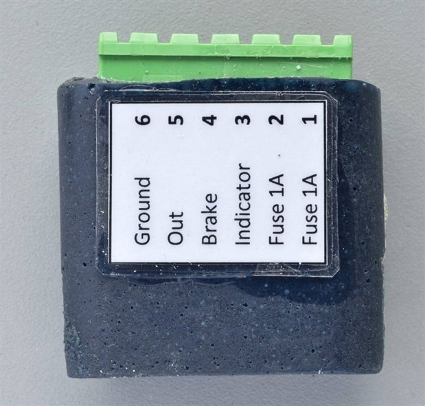
We came to an arrangement where he provided some of these stickers

and I made him some modules
I had built the units and tested them before delivering them, but last week after the LED lamps arrived, I got a phone call and he was having some issues.
Testing
The testing needed to simulate the product in everyday use. This includes indicators only, brake only and combinations of brake and indicator.
What better use for an Arduino and three relays.
The code is below
/*
  Tail light Tester
  This turns on several relays and is used to test the LED Tailight boards
  Sequence is :-
  Left Ind
  Right Ind
  Brakes
  Brake plus Left
  Brake plus Right
  Left plus Brake
  Right plus Brake


*/

//Define Outputs
const int L_Indicator = 12;
const int L_Indicator_LED = 11;
const int Brake     = 10;
const int Brake_LED = 9;
const int R_Indicator = 8;
const int R_Indicator_LED = 7;

int x=0;

// the setup function runs once when you press reset or power the board
void setup() {
  // initialize digital pin LED_BUILTIN as an output.
  pinMode(LED_BUILTIN, OUTPUT);
  pinMode(L_Indicator, OUTPUT);
  pinMode(L_Indicator_LED, OUTPUT);
  pinMode(Brake, OUTPUT);
  pinMode(Brake_LED, OUTPUT);
  pinMode(R_Indicator, OUTPUT);
  pinMode(R_Indicator_LED, OUTPUT);

}

// the loop function runs over and over again forever
void loop()
{
  delay (1000);

  // L_Indicator ON
  for (x = 0; x <=10; x++)
  {
    digitalWrite(L_Indicator, HIGH);
    digitalWrite(L_Indicator_LED, HIGH);
    delay (500);
    digitalWrite(L_Indicator, LOW);
    digitalWrite(L_Indicator_LED, LOW);
    delay (500);
  }

  delay (1000);

  // R_Indicator ON
  for (x = 0; x <=10; x++)
  {
    digitalWrite(R_Indicator, HIGH);
    digitalWrite(R_Indicator_LED, HIGH);
    delay (500);
    digitalWrite(R_Indicator, LOW);
    digitalWrite(R_Indicator_LED, LOW);
    delay (500);
  }

  delay (1000);

      // Brakes ON
      digitalWrite(Brake, HIGH);
      digitalWrite(Brake_LED, HIGH);
      delay (5000);

      // Brakes OFF
      digitalWrite(Brake, LOW);
      digitalWrite(Brake_LED, LOW);

  delay(1000);                       // wait for a second


// Brake plus Indicator
      // Brakes ON
      digitalWrite(Brake, HIGH);
      digitalWrite(Brake_LED, HIGH);
      delay (500);

        // L_Indicator ON
        for (x = 0; x <=10; x++)
        {
          digitalWrite(L_Indicator, HIGH);
          digitalWrite(L_Indicator_LED, HIGH);
          delay (500);
          digitalWrite(L_Indicator, LOW);
          digitalWrite(L_Indicator_LED, LOW);
          delay (500);
        }

  delay(1000);                       // wait for a second

      // Brakes OFF
      digitalWrite(Brake, LOW);
      digitalWrite(Brake_LED, LOW);

  delay(1000);                       // wait for a second

       // Brakes ON
      digitalWrite(Brake, HIGH);
      digitalWrite(Brake_LED, HIGH);
      delay (500);

        // R_Indicator ON
        for (x = 0; x <=10; x++)
        {
          digitalWrite(R_Indicator, HIGH);
          digitalWrite(R_Indicator_LED, HIGH);
          delay (500);
          digitalWrite(R_Indicator, LOW);
          digitalWrite(R_Indicator_LED, LOW);
          delay (500);
        }

  delay(1000);                       // wait for a second

      // Brakes OFF
      digitalWrite(Brake, LOW);
      digitalWrite(Brake_LED, LOW);

  delay(1000);                       // wait for a second

  // Indicator plus Brake
        // L_Indicator ON
        for (x = 0; x <=10; x++)
        {
          digitalWrite(L_Indicator, HIGH);
          digitalWrite(L_Indicator_LED, HIGH);
          delay (500);
          digitalWrite(L_Indicator, LOW);
          digitalWrite(L_Indicator_LED, LOW);
          delay (500);
          if (x ==4)
          {
            // Brakes ON
            digitalWrite(Brake, HIGH);
            digitalWrite(Brake_LED, HIGH);
          }
        }

        // Brakes OFF
        digitalWrite(Brake, LOW);
        digitalWrite(Brake_LED, LOW);


        delay(1000);                       // wait for a second

        // R_Indicator ON
        for (x = 0; x <=10; x++)
        {
          digitalWrite(R_Indicator, HIGH);
          digitalWrite(R_Indicator_LED, HIGH);
          delay (500);
          digitalWrite(R_Indicator, LOW);
          digitalWrite(R_Indicator_LED, LOW);
          delay (500);
          if (x ==4)
          {
            // Brakes ON
            digitalWrite(Brake, HIGH);
            digitalWrite(Brake_LED, HIGH);
          }
        }

        // Brakes OFF
        digitalWrite(Brake, LOW);
        digitalWrite(Brake_LED, LOW);

}
As you can see it cycles around the various options, and I tested the modules before and after casting them.
The Wrong
Since I had tested these prior to delivering them, I had every reason to suspect that a wiring issue was the cause, and arranged to call around to his place and assist.
There were some minor issues with lack of stripping back the insulation on one earth, the rest seemed to be correctly wired.
Sadly both of the units showed different issues, but when I put them back on the bench tester, only one had a faulty input.
In the interests of good engineering, it's always useful to know what failed and see if you can determine why.
However these were encased in resin, and worse, it was coloured so the exact placement of the parts was invisible.
Several hours later with a Dremel and different tips exposed enough of the internals to do some testing.

Since there are three different components that could be at fault, I was trying to be careful and not damage the components.
I've always found that you need to be able to replicate the fault, in order to prove you've fixed it.
I was able to replicate the fault before attacking it, and again when exposed, so my work didn't cause a second issue. ... 
Fault identification
I can really only get to the bottom of the board which is enough to verify what I suspect is the problem.
Thankfully jw0752 had sent me some of his Intrusive Meter Probes to test.
Meter Lead - JW special probes
These were able to penetrate the resin that was still on the veroboard and ensured the meter made good contact with the components.

While the unit has failed, the exact cause will never be truly known.
It could have been a wiring mistake in the vehicle that got rectified, or something else.
With the complexity of the wiring and the admission that vehicle wiring is not something he is confident with, it's possible there was a problem.
I'm not concerned if the fault was due to a mistake, but it would be nice to know that.
While I was helping, there were two other issues that I was able to solve, so any inconvienience is more than compensated for, and the failure isn't holding up the build.
As we've said before on this forum, it's not the failure but the after sales service that is more important.
Conclusions
The design has some limitations and I did look at fitting bigger transistors.
Sadly the next size transistor is both much more expensive and much larger, but I've still got an issue with 1A diodes.
The design is fine for one off's but it's time to design a board and use smd components.
It means they are much easier and less time consumming to make, along with the alignment in the mould.
The change to smd may provide some cheaper options for uprating it to handle 5A.
In the meantime I've made two new modules, tested them and I'm about to cast them tomorrow.
This time I have a better plan to hold the connector the right distance out in the mould, along with better measuring of the resin amount needed ..... 
(edit ... the support worked but despite measuring the amount and not removing anything for the contents, it was short .... more investigating required)
Mark
Top Comments