


A week or so ago I wrote a short blog about a variable AC isolated bench power supply that I wanted to build. See the following Blog:
An Extreme Ripple Power Supply Build
The idea was just a seed and a pile of assorted resources. Just as I hoped, four of my friends here on element 14 stepped up and gave me some great advice and collaboration on the build. I want to specially thank: genebren , Gough Lui , three-phase , and jc2048 without whose suggestions and ideas I could not have completed the project as successfully.
The purpose of this build was to produce a bench AC power supply with 160 volts output at 2 or 3 amps. It seems that weekly, one project or another needs an AC source of one voltage or another. My present AC power supply is about 50 years old and it is time for an update.
I began with a rough draft of a schematic which I published in the previous blog. There were mistakes and improvements to be made as pointed out by my collaborators. Here is the schematic of the final build of the power supply:

Some of the great ideas that were suggested to me were to add an MOV to the input to protect against spikes, add fuses in the secondary and output of the unit, provide a voltage fail safe so that the unit could not be powered on while set to a lethal voltage level, and a high voltage alert light. The final build has all of these features.
As usual I began this project with a slow trip through my parts graveyard looking for resources. I almost never produce a design and then look for the parts. It is always find the parts and then design an interface between them. The central parts central to the build were a transformer, where 115 VAC on the primary would give me an isolated 130 VAC on the secondary, a small variac, and a salvaged case from a piece of 1960s vintage dental equipment.

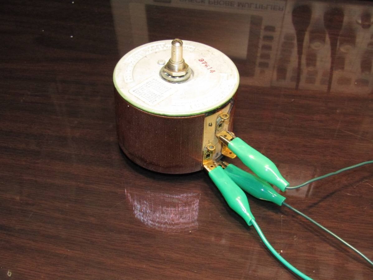
Here are the transformer and the variac in the early proof of concept experiments. It is important to bread board or jumper wire experiments of the build before proceeding so that one will eventually get the desired results.
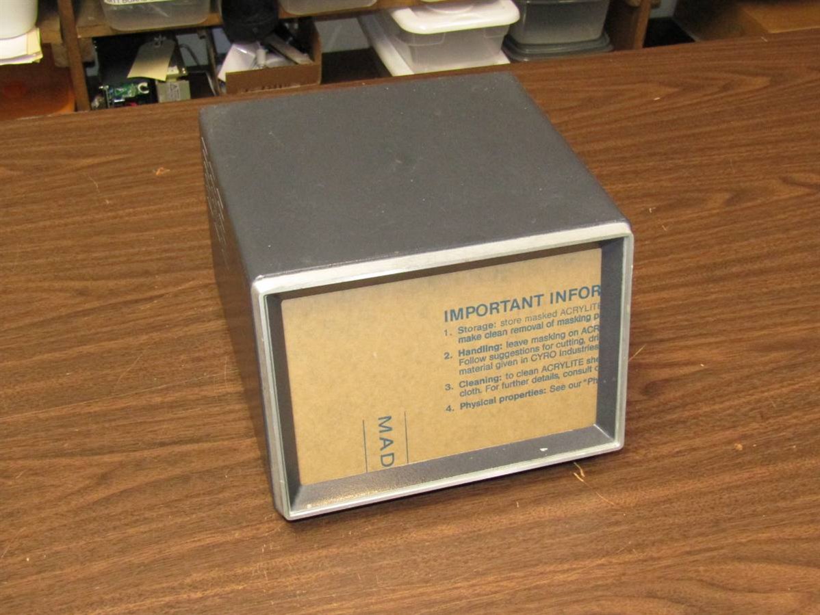
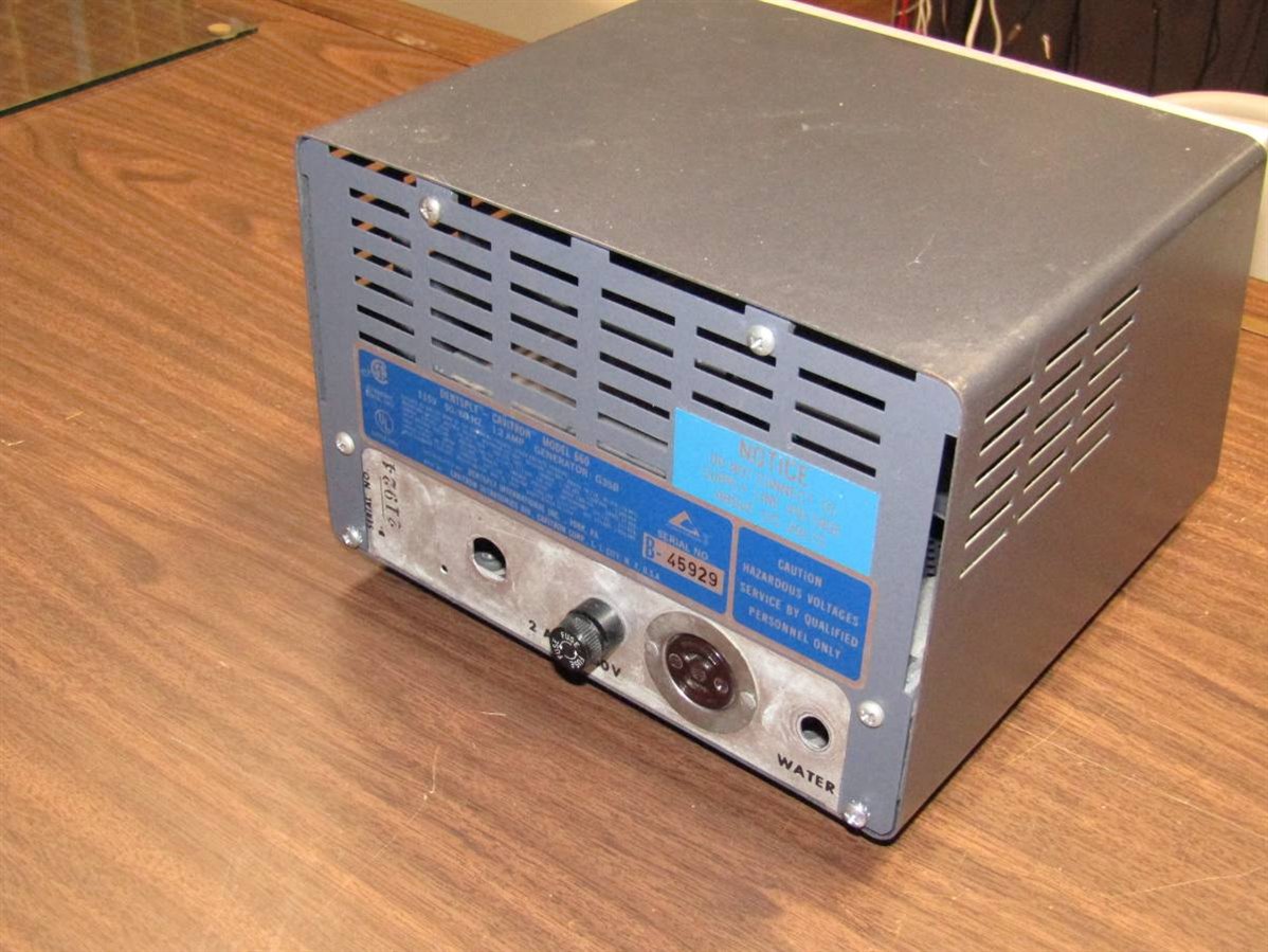
The case was hopefully going to be big enough to house everything. It was a heavy steel case with an old fashioned chassis inside. The chassis would have to be substantially modified before it would properly hold the components. I began by spray painting the case a nice off white color. The front panel was a piece of black opaque plexiglass. I have used this type of front panel on many of my builds as it is easy to work with and when labeled with white on clear label tape it looks good enough for me.
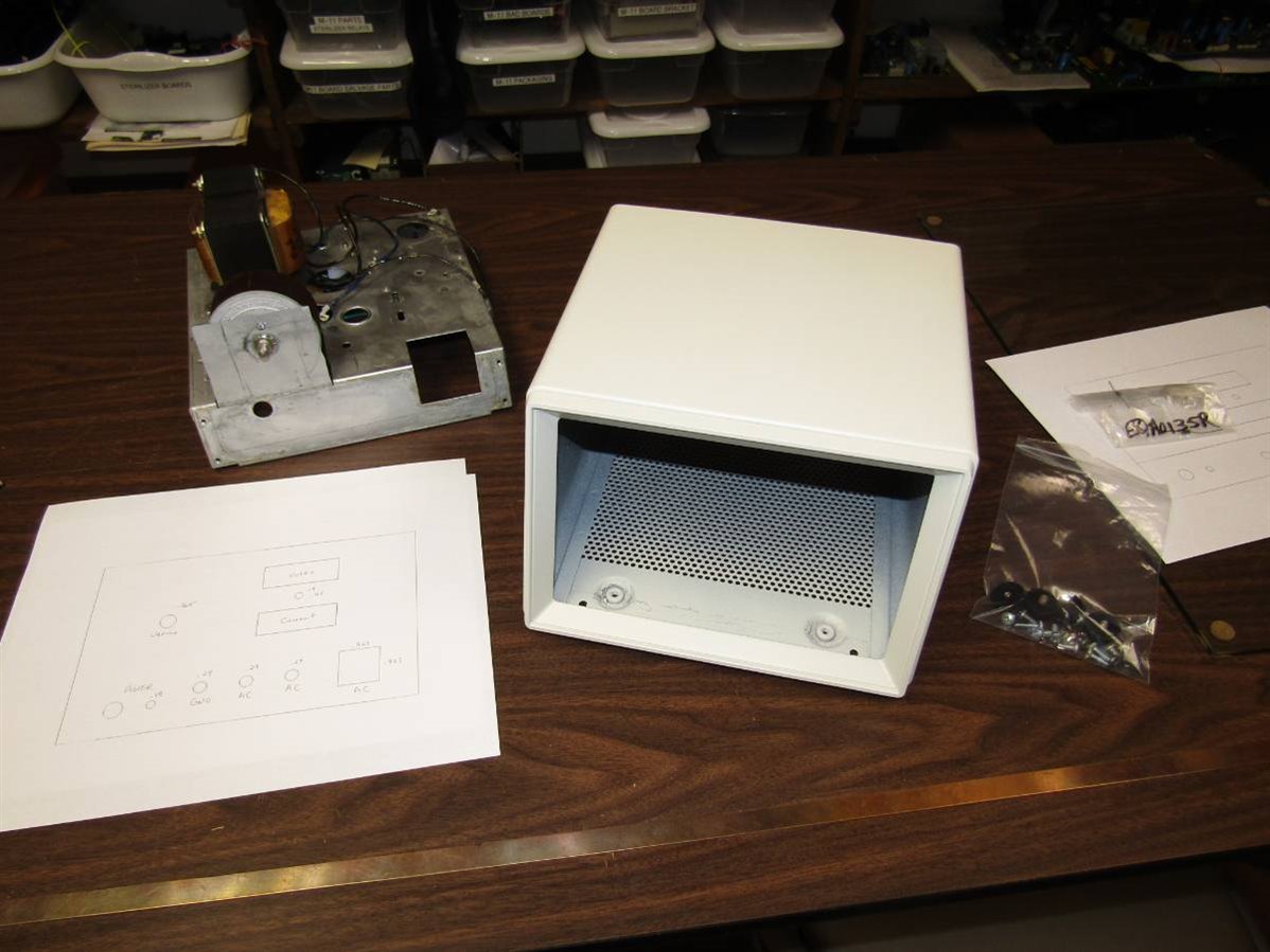
Here is the painted case and to the left is the chassis where I have mounted the isolation transformer and the variac. For the variac I had to cut the floor of the chassis and fold it up to make an extension of the front metal. This made room for the body of the variac as well as providing extra support for the front plate. As the project continued this was the first of several cuts and bends that needed to be done to the chassis. In the front left you can see the preliminary layout of the front panel. At this time the front panel meters had not come and so I had estimated their dimensions. Time would prove that I had greatly underestimated their size and many of the challenges to finishing this project revolved around how to integrate them into the case. Eventually I had to cut more of the front of the chassis out and extend the square hole that you can see in this picture to the left, almost all the way to the variac plate.
Once I had the primary components on the chassis I began to populate the unit with minor components and finally I began the initial wiring.
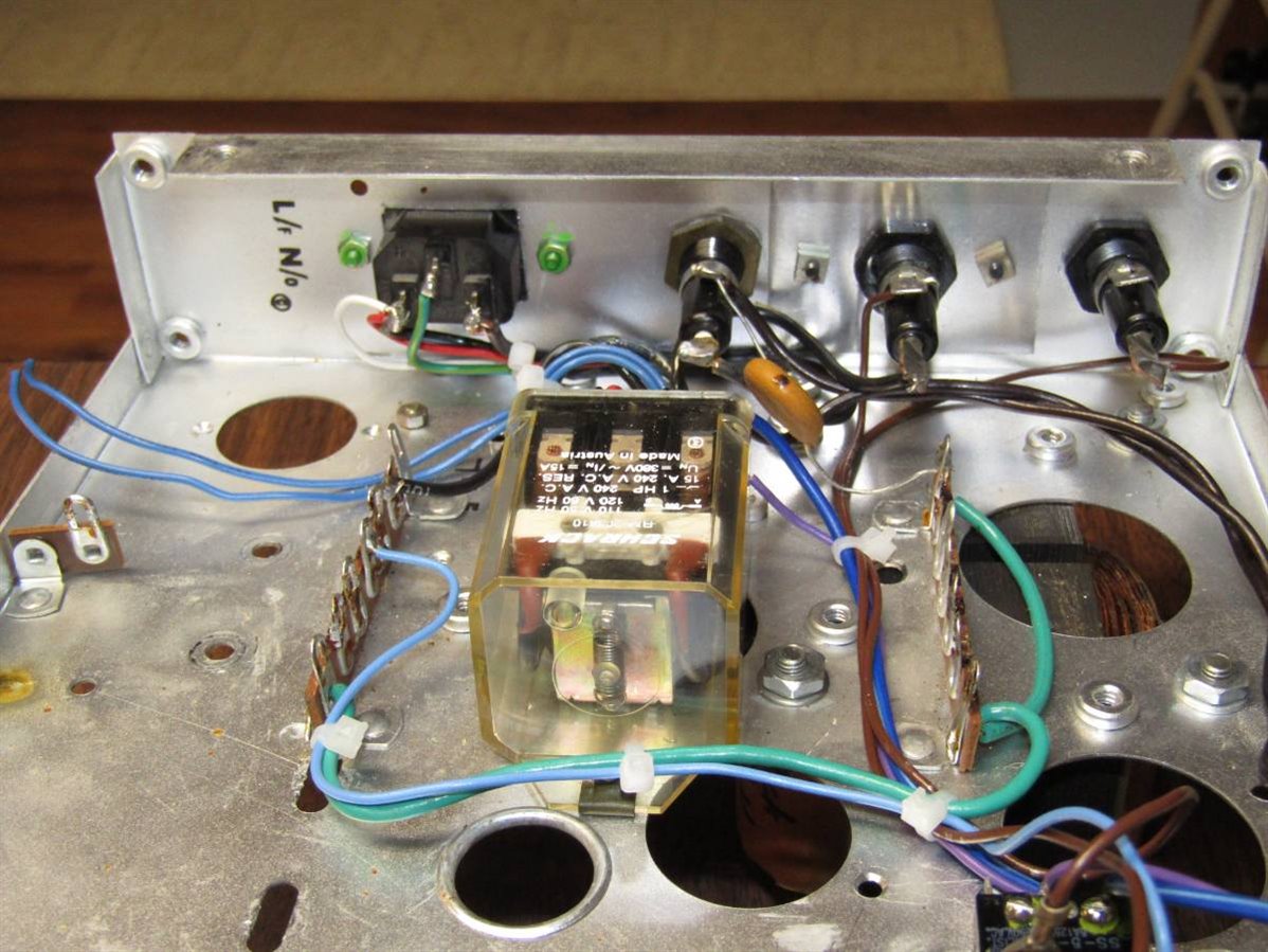
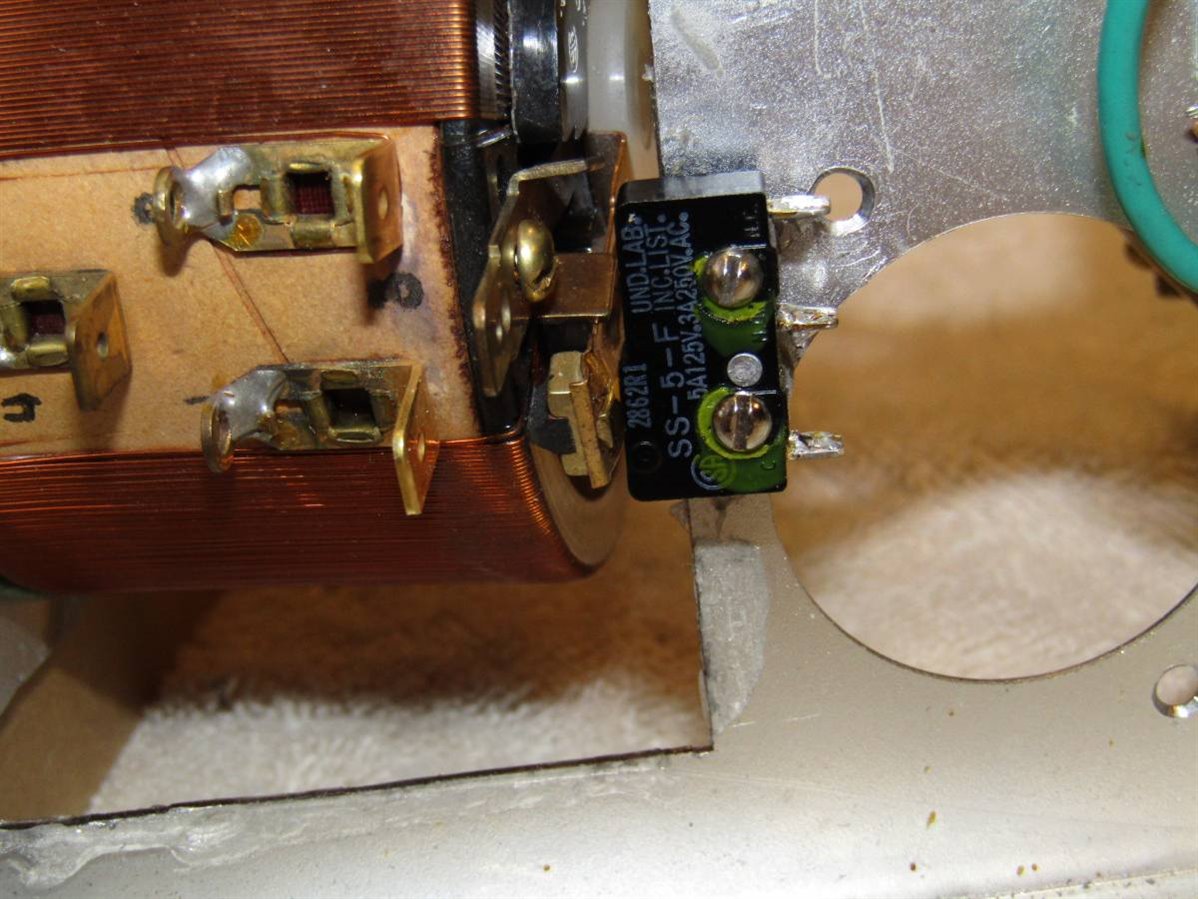
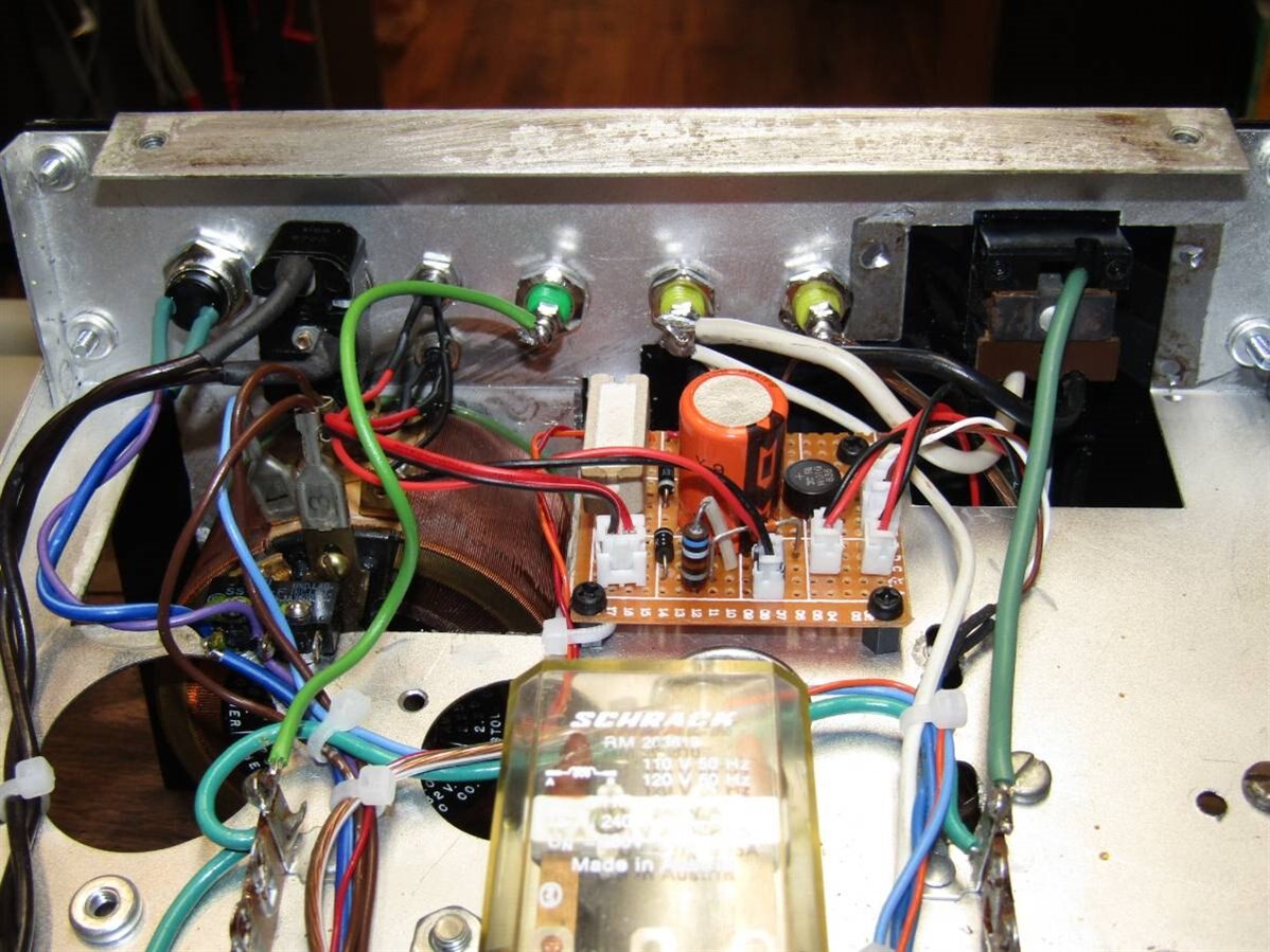
In this picture you can see the fuses for the primary, secondary and output circuits that were recommended by my element 14 collaborators as well as an AC relay that will be used in the circuit that will prevent the unit from being turned on if the variac is not in the low voltage position. In the lower right corner of the picture you can see the microswitch , better picture to the right, that senses the zero volt position of the variac. When the wiper of the variac comes to the full off position a small epoxy ramp on top of it actuates the microswitch. If this switch or the override switch is not closed the relay will not actuate and latch. When I installed the microswitch it was necessary to cut slots for the mounting screws so that the position relative to the variac wiper could be adjusted.
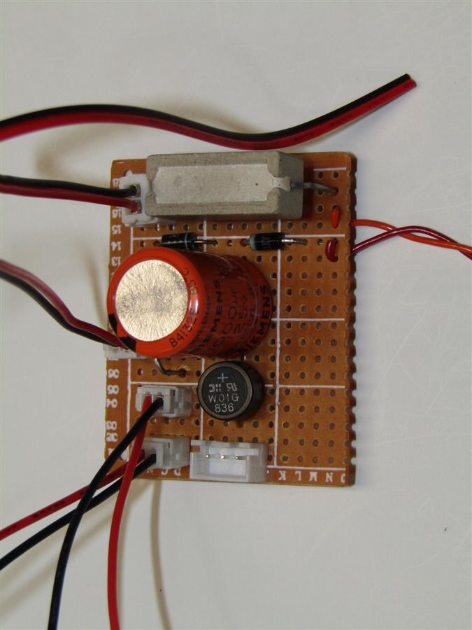
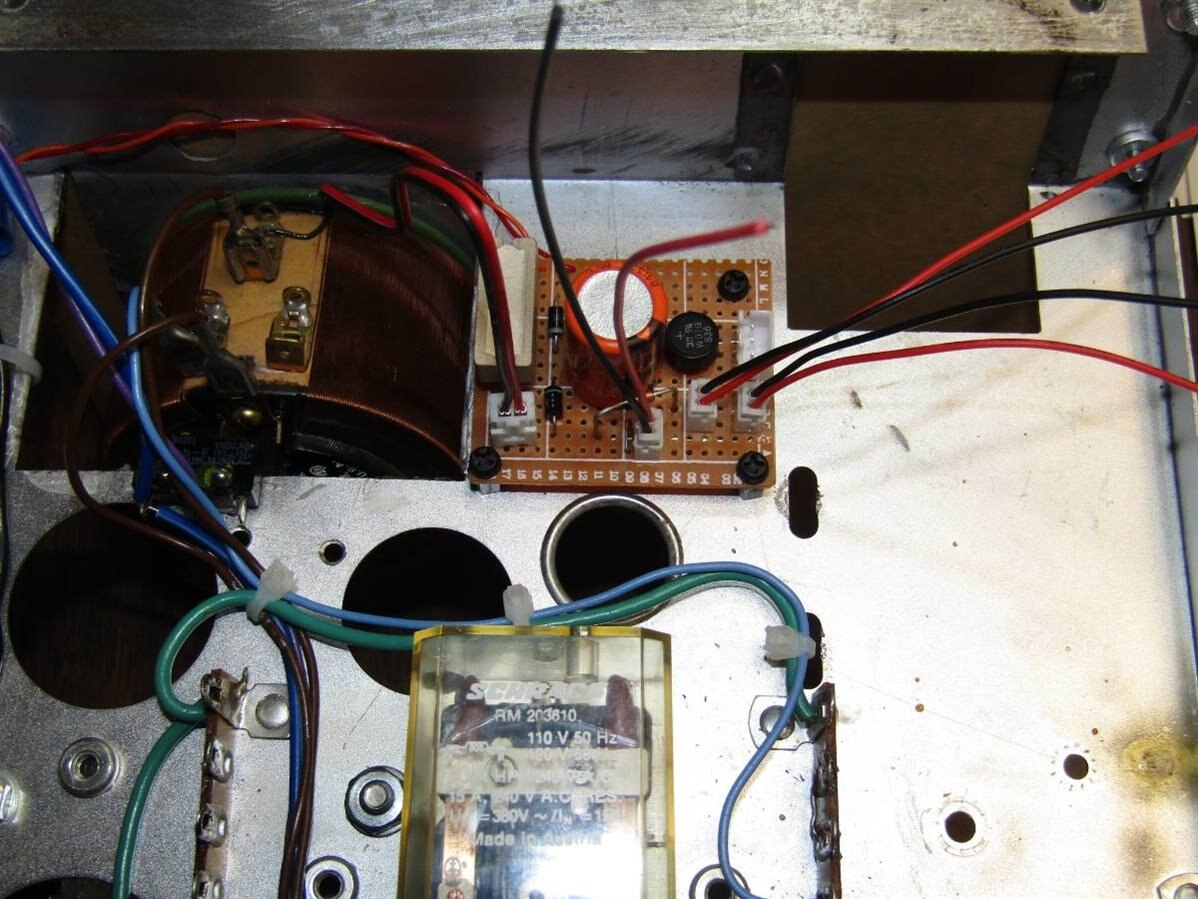
To get the 12 volts DC that would power the voltmeter and ammeter circuits a small power supply board was built. This board was powered by a separate transformer. You can see it on the chassis at the back in later pictures. Since there was adequate room on the board the components for the high voltage sense circuit were also added. This power supply also drives the power on indicator LED.
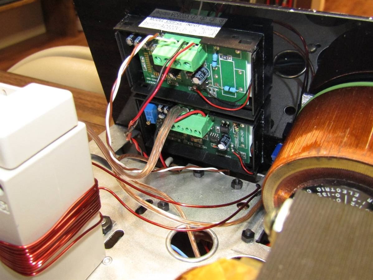
The small circuit board was mounted on standoffs near the front panel so that it would be close to the meters and indicator LEDs.
The meters for the unit finally arrived and with them the surprise that they were much bigger than I had assumed.

Here is a picture of the ammeter. The larger size forced me to return to the plan for the front panel and begin searching for every millimeter of space. The front panel on which they were to be mounted had conflicts with the chassis and there was the ultimate need for everything to fit inside the bezel of the outer case. It was very close and don't tell anyone but in the end the fit inside the bezel of the outer case is not perfect. Fortunately the black plastic panel hides the slight gap very well.
Another challenge that I left for the arrival of the meters was the fact that the ammeter was designed to measure up to 100 amps and the most I anticipated measuring was 3 amps. This would mean that I would not be making good use of the range of the ammeter and that my current measurement accuracy would suffer. The ammeter came with a huge current transformer.
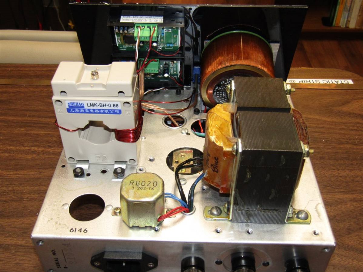
Here you can see the current transformer mounted to the chassis. Fortunately once I got away from the crowded front panel there was lots of room in the body of the unit. I decided that I would put two windings on the current transformer and install a SPDT toggle next to the ammeter so that I could choose between the single 0 to 100 amp display on the meter to a more detailed 0 to 10 amp display. As you can see on the right side of the current transformer I have wound the current carrying conductor 10 times to produce the compressed range. On the left side of the transformer we have the single pass through of the 0 to 100 range. I experimented briefly with moving the decimal point on the meter but total lack of technical information made this a difficult and risky modification. In the end I decided to make use of a unit of current that is seldom encountered. "The Deciamp". Yes, when the toggle is switched to the 0 to 10 amp range the meter displays the current in deciamps. While not totally desirable it adds some character to the unit and it is worth the extra accuracy that is displayed by the meter. These meters were quite inexpensive, less than $15 each and while they work well for this application they take their time reading and displaying the voltage and current. I think they refresh twice a second and the 1 to 100 amp range will sometimes take 3 to 4 seconds to settle on the correct display. In the short video at the end of this blog you will see when I switch from 4.6 deciamps to amps the display reads 2 then 3 and while I don't wait for it to get there it will eventually display 4.
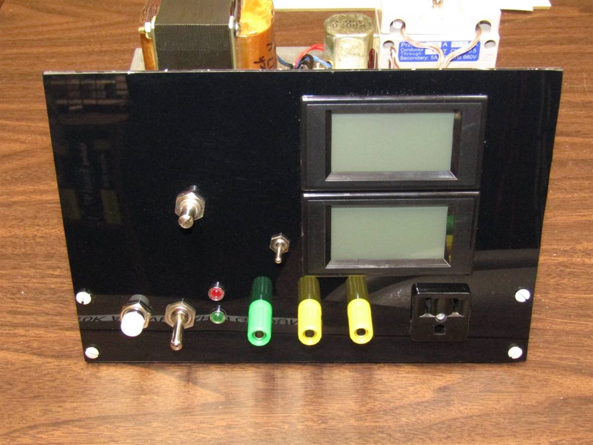
Here is the front control panel prior to labeling. The second picture shows the tightness behind the control panel and the way it was necessary to cut into the chassis so that the back of the meters had room.
Here is the underside of the chassis behind the front control panel.
When I finished the build at 2 AM last night I did not dare turn it on and test it. I have made this mistake in the past and if anything doesn't work correctly I would find myself pulling an all nighter trying to find my mistakes and debug the unit. It is much better to assume the best and go to bed and test it in the morning. Fortunately the morning light brought smiles as the unit worked as planned. The front panel was labeled as well as the back fuse plate of the unit. I enlisted the help of the boss to make a short demo video which is posted below.
Finally thank you to element 14 for providing this site where I can get help from friends in England, USA, and Australia on my projects.
John
Top Comments
-

ralphjy
-
Cancel
-
Vote Up
+5
Vote Down
-
-
Sign in to reply
-
More
-
Cancel
-

jw0752
in reply to ralphjy
-
Cancel
-
Vote Up
+4
Vote Down
-
-
Sign in to reply
-
More
-
Cancel
Comment-

jw0752
in reply to ralphjy
-
Cancel
-
Vote Up
+4
Vote Down
-
-
Sign in to reply
-
More
-
Cancel
Children