


If you haven't been following this series here are the links to the first two chapters:
In this chapter I will show you the mechanism that was built to turn the main water valve entering the house the 90 degrees necessary to close it. Here is a picture of the valves and water meter at the service entrance:
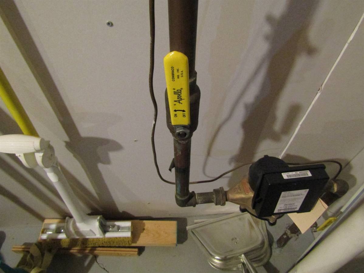
mcb1 used his sharp observation and noticed that the best valve to work with would be the one in the lower right of the picture as this would protect from all leaks or problems that might come up with the water meter as well as other leaks in the plumbing system. Unfortunately the position of this valve and the direction that it must be turned did not lend itself to a solution. I decided that the water meter hopefully would be a low risk part of the system and concentrated my efforts on the valve in the center of the picture. This valve must be rotated clockwise 90 degrees to close it. It was determined that approximately 11 Newton-meters of torque was needed to smoothly turn the valve. The valve was only 12 cm long so this brought the force needed on the end of this lever to 90 Newtons. The process of coming up with a way to apply this force in a reasonable direction indicated that an angle addition to the lever would perhaps be useful.
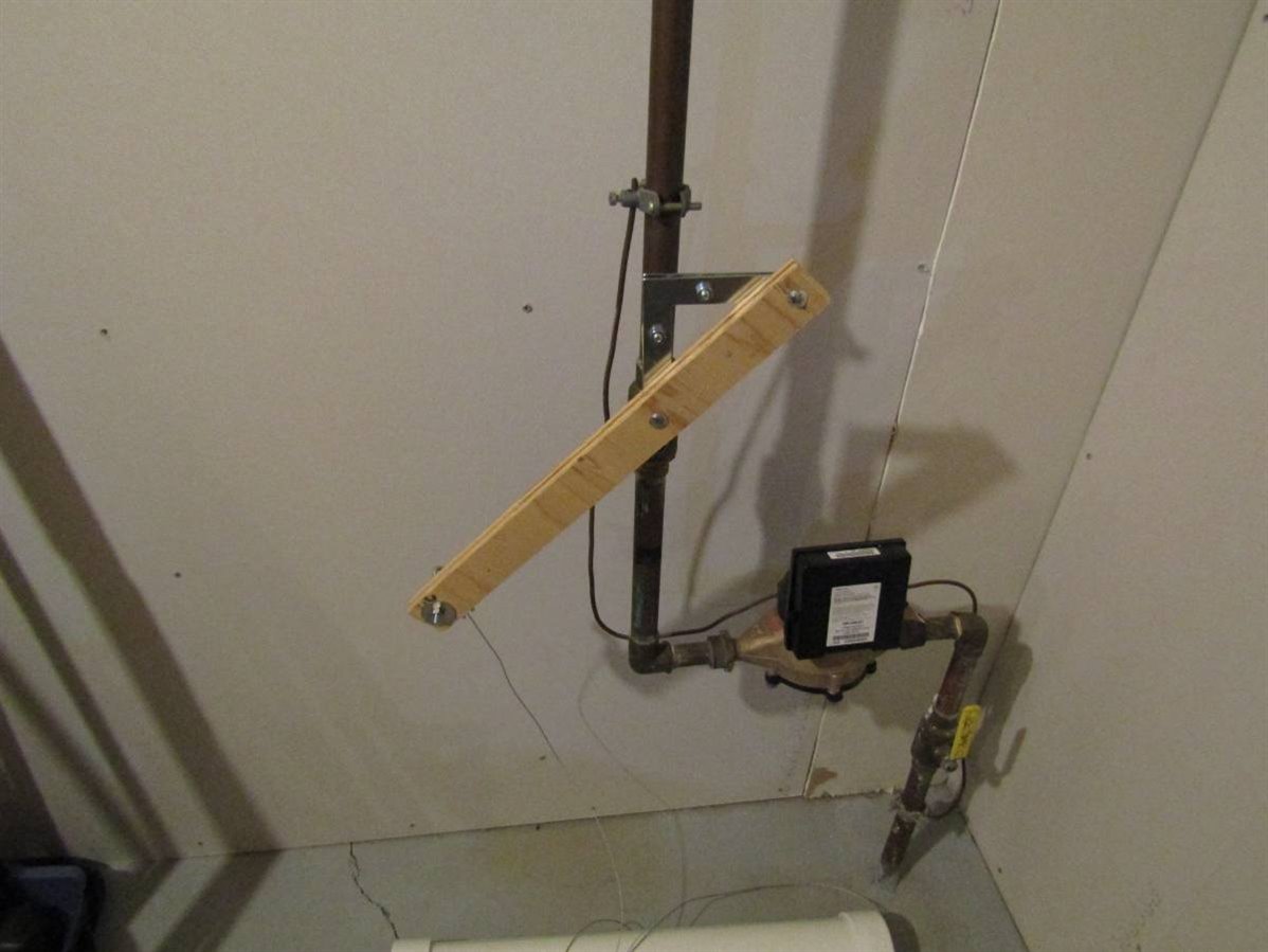
After several failed attempts a longer lever arm was added which reduced the force needed. I wanted to use gravity to move the lever. Gravity would supply a steady force as the valve is rotated in contrast to the non-linear force supplied by a spring. Thin steel cable was attached to the end of the lever arm and run up to the ceiling and through a pulley and then attached to a weight made of PVC pipe. The PVC was filled with stones until the desired weight of approximately 6 kg was obtained.

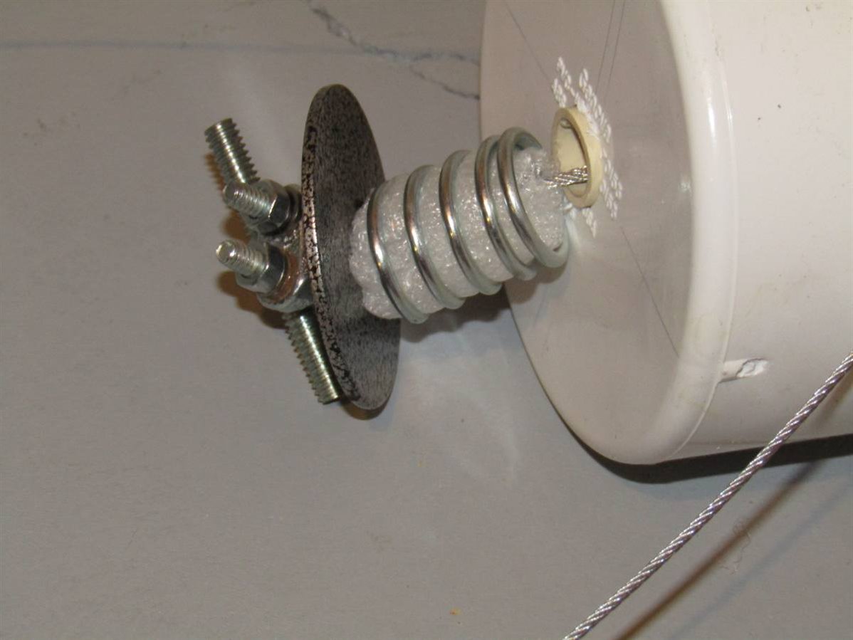
The PVC weight was constructed so that a smaller internal piece of PVC ran the length of the weight. The wire cable was threaded through the center pipe and secured at the bottom as indicated in the picture. A spring shock absorber was fabricated at the bottom to minimize the impulse force to the valve as it hits its stop position.
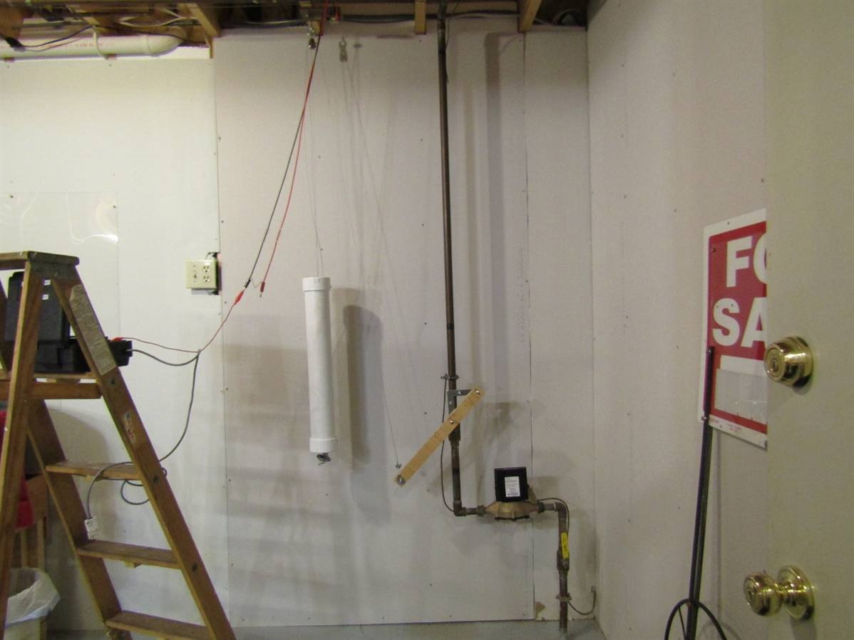
Here is the layout of the system with the weight suspended and the cable running over the pulley and down to the lever arm on the valve. The next problem was to design some type of latch and trigger so that the weight could be held up releasing tension on the wire to the valve lever until an electric signal releases it to fall and close the valve. Ideas from mcb1 and dougw provided inspiration and here is what I eventually settled on:
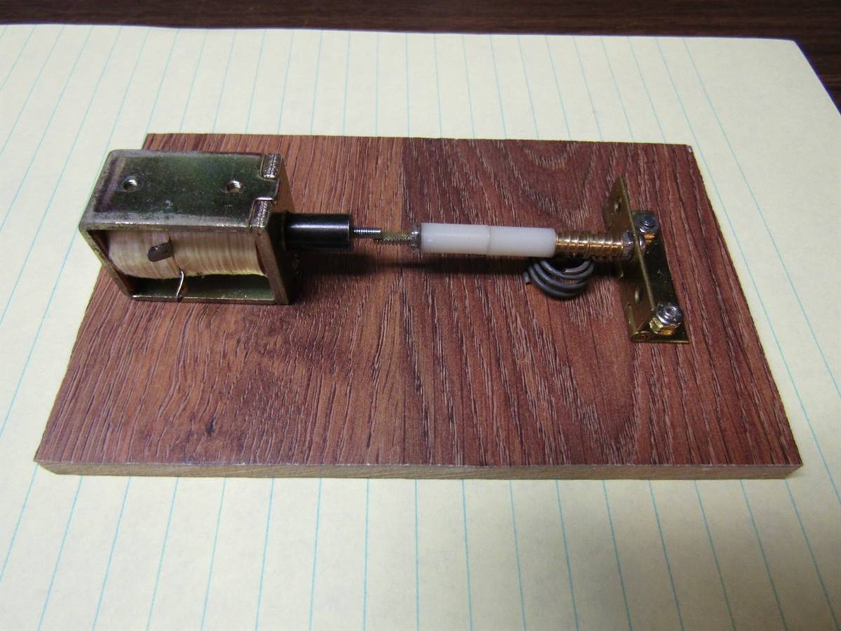
Here we have a 12 volt solenoid that I salvaged from an 8 track tape player many years ago. A long machine screw is mounted through a hinge that is secured to the board. Nylon and other spacers are over the screw and held in place with a nut on the end near the solenoid. You can see a spring compressed under the screw to simulate the tension that the weight would normally be supplying. When the solenoid retracts it releases the long screw to pivot on the hinge and release the cable. By positioning the cable to the weight very close to the hinge a minimum amount of force is presented to the solenoid trip point. This solenoid latch board was attached to the ceiling above the weight and a separate cable was attached to the weight that held it just high enough to take the force off the cable going to the valve.

You can see an improvement that was made to the trip point where nylon bushings have been added to the solenoid and the screw. This lowers the friction at the trip point and makes it easier for the solenoid to dependably retract. Millie made a video of me making a test of this part of the project. For a temporary test I have wired the solenoid so that I can apply 12 volts from a battery.
Now that I have a functional mechanical way to close the valve we can proceed with the design of a control to tie the Sensors of Chapter 2 to the Mechanics of Chapter 3. The construction of this control is progressing well at this point and I should have a finished system to demonstrate in a few days.
John
Top Comments