element14 Community
element14 Community
    Register Log In
  • Site
  • Search
  • Log In Register
  • Community Hub
    Community Hub
    • What's New on element14
    • Feedback and Support
    • Benefits of Membership
    • Personal Blogs
    • Members Area
    • Achievement Levels
  • Learn
    Learn
    • Ask an Expert
    • eBooks
    • element14 presents
    • Learning Center
    • Tech Spotlight
    • STEM Academy
    • Webinars, Training and Events
    • Learning Groups
  • Technologies
    Technologies
    • 3D Printing
    • FPGA
    • Industrial Automation
    • Internet of Things
    • Power & Energy
    • Sensors
    • Technology Groups
  • Challenges & Projects
    Challenges & Projects
    • Design Challenges
    • element14 presents Projects
    • Project14
    • Arduino Projects
    • Raspberry Pi Projects
    • Project Groups
  • Products
    Products
    • Arduino
    • Avnet & Tria Boards Community
    • Dev Tools
    • Manufacturers
    • Multicomp Pro
    • Product Groups
    • Raspberry Pi
    • RoadTests & Reviews
  • About Us
  • Store
    Store
    • Visit Your Store
    • Choose another store...
      • Europe
      •  Austria (German)
      •  Belgium (Dutch, French)
      •  Bulgaria (Bulgarian)
      •  Czech Republic (Czech)
      •  Denmark (Danish)
      •  Estonia (Estonian)
      •  Finland (Finnish)
      •  France (French)
      •  Germany (German)
      •  Hungary (Hungarian)
      •  Ireland
      •  Israel
      •  Italy (Italian)
      •  Latvia (Latvian)
      •  
      •  Lithuania (Lithuanian)
      •  Netherlands (Dutch)
      •  Norway (Norwegian)
      •  Poland (Polish)
      •  Portugal (Portuguese)
      •  Romania (Romanian)
      •  Russia (Russian)
      •  Slovakia (Slovak)
      •  Slovenia (Slovenian)
      •  Spain (Spanish)
      •  Sweden (Swedish)
      •  Switzerland(German, French)
      •  Turkey (Turkish)
      •  United Kingdom
      • Asia Pacific
      •  Australia
      •  China
      •  Hong Kong
      •  India
      • Japan
      •  Korea (Korean)
      •  Malaysia
      •  New Zealand
      •  Philippines
      •  Singapore
      •  Taiwan
      •  Thailand (Thai)
      • Vietnam
      • Americas
      •  Brazil (Portuguese)
      •  Canada
      •  Mexico (Spanish)
      •  United States
      Can't find the country/region you're looking for? Visit our export site or find a local distributor.
  • Translate
  • Profile
  • Settings
Personal Blogs
  • Community Hub
  • More
Personal Blogs
John Wiltrout's Blog Bench Suppy for Young Experimenter
  • Blog
  • Documents
  • Mentions
  • Sub-Groups
  • Tags
  • More
  • Cancel
  • New
  • Share
  • More
  • Cancel
Group Actions
  • Group RSS
  • More
  • Cancel
Engagement
  • Author Author: jw0752
  • Date Created: 16 Dec 2014 1:01 AM Date Created
  • Views 1503 views
  • Likes 4 likes
  • Comments 23 comments
  • overload_protection
  • power_supply
  • regulated
Related
Recommended

Bench Suppy for Young Experimenter

jw0752
jw0752
16 Dec 2014

Recently my 8 year old grandson, Christian, has taken to hooking switches, lights, motors and other pieces of salvaged electronics together. When I discovered that he was using an old 12 volt wall wart adapter to power his creations I realized that I could bring some of my new found electronic knowledge together to make a better alternative for him.


My list of important features:


Safe and secure form line voltage

Overload and Short Protection

Reasonable Current at 0 to 12 Volts output.

Easy to read meters

Easy to use controls.


While the unit will be plugged into the wall I have used a grounded metal enclosure and a hospital grade plug. Additional protection will be provided by my son who has agreed to supervise the experimentation.


Thanks to Don Hersey I have the perfect component to use for the output driver. The LM395 Darlington IC can provide 2.2 Amps at my max target voltage of 12 volts. Furthermore the LM395 is thermally and overload protected by internal circuitry. This will give me peace of mind as there is no doubt that many of Christian's hookups will tie V plus directly to ground. Recent tutorials by Peter Oakes have given me the designs I will need to complete the rest of the power supply circuit. I will use a 6 volt Zenner diode to create a voltage reference and a TLE2142 rail to rail op amp to drive the LM395. Current limiting will not be necessary as the LM395 has this all built in. Pre-testing has indicated that the output leads can be shorted together with no damage to the LM395 or any other part of the circuit.


The base power will come from a 15 volt chassis mount transformer, a full wave bridge, and a filter capacitor. I am going to mount these items into a nice heavy gauge aluminum case that was originally a piece of dental equipment. In the cover of the case there will be room for a voltmeter and ammeter. The 2.75 mm thick aluminum case will provide an excellent heat sink for the LM395 and bridge rectifier.


Here is the schematic for the unit.


image


Here are some pictures of the finished unit.


         imageimage


        imageimage


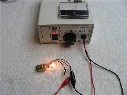
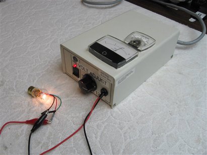
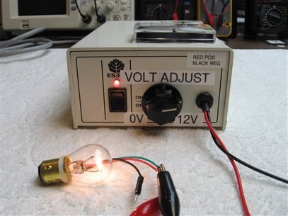
This power supply should provide my grandson with a way to power his experiments and still protect him from dangerous voltages and currents. Thanks again to Don and Peter for their contributions.


John

  • Sign in to reply

Top Comments

  • michaelwylie
    michaelwylie over 11 years ago +1
    Love the Grandpa author on your schematic. Nice build.
  • mcb1
    mcb1 over 11 years ago +1
    Nice work ... and REAL meters. One minor suggestion is an Output switch to instantly kill the volts, and allow setting before applying. Mark
  • shabaz
    shabaz over 11 years ago +1
    Nice! I bet there are not many lucky 8-year olds with equipment with analog meters : )
  • D_Hersey
    D_Hersey over 11 years ago

    What a nice box!


    It is hard to demarcate the boundary to the rococo with these things.  I had a philosophy teacher use an ancient Greek term for 'tumor doctor' to call the process by which an artist quits working on a particular work.  If I ever find that word again, I will be elated! He held that if you kept improving something ad infinitum you will come to sink the project.  That said:


    You could put PBs by the meters that would verify that the needles weren't stuck.  They would mid-scale the meters when depressed.


    You could have an OVP crowbar:

    http://www.ti.com/lit/ds/symlink/lm431.pdf

    [fig 20.]


    For current-sense, we could put a 10 - 25 seimens conductor in the collector leg of our power Q.  We would be neglecting our base current contribution, to fix this we could put an NPN in front of the power Q in darlington configuration, or we could change the power Q to a N MOSFET on a generously-scaled heat spreader.


    This would generate a (in the case of the ten seimens conductor) 100 mV drop from the top at the ampere of flow at which you want to clip.  You need to use a fuse of slightly greater current capacity so it doesn't trip first.


    To detect this you would need a RRIO comparator.  There could be a switchable reference from the top to set the trip point.  Upon the crossing of the comparator's threshold, we trigger a F/F which 1)  Floods the inverting terminal of the op-amp with current so as to saturate it and shut down (or by another method) the output stage.  2) Turns on a red light.  The other side of the F/F is a PB that won't need much debouncing.  You might need to provide some dynamic de-sensing (likely a capacitor) to not be hyper on spikes.  Of course, provisioning will have to be made to reset the F/F on power-up.


    Use comparators or si-gate CMOS for the F/F and it won't need a local regulator.

    • Cancel
    • Vote Up 0 Vote Down
    • Sign in to reply
    • More
    • Cancel
  • jw0752
    jw0752 over 11 years ago in reply to D_Hersey

    Thanks Don, As usual your post is full of good information. I will followup and check out the Zenner Manual and PREM Transformers.

    John

    • Cancel
    • Vote Up 0 Vote Down
    • Sign in to reply
    • More
    • Cancel
  • jw0752
    jw0752 over 11 years ago in reply to mcb1

    Thanks Mark, This is a good suggestion and easy to implement. I will make it happen.

    John

    • Cancel
    • Vote Up 0 Vote Down
    • Sign in to reply
    • More
    • Cancel
  • Robert Peter Oakes
    Robert Peter Oakes over 11 years ago

    I like it, I recognize the basis of the circuit, nice to see you applying what we are learning on our journey together, a nice addition might be a current limit, not sure there the pot would fit though image, this way he can protect his projects when not sure of the current requirements


    Well done


    Peter

    • Cancel
    • Vote Up +1 Vote Down
    • Sign in to reply
    • More
    • Cancel
  • shabaz
    shabaz over 11 years ago

    Nice! I bet there are not many lucky 8-year olds with equipment with analog meters : )

    • Cancel
    • Vote Up +1 Vote Down
    • Sign in to reply
    • More
    • Cancel
<>
element14 Community

element14 is the first online community specifically for engineers. Connect with your peers and get expert answers to your questions.

  • Members
  • Learn
  • Technologies
  • Challenges & Projects
  • Products
  • Store
  • About Us
  • Feedback & Support
  • FAQs
  • Terms of Use
  • Privacy Policy
  • Legal and Copyright Notices
  • Sitemap
  • Cookies

An Avnet Company © 2026 Premier Farnell Limited. All Rights Reserved.

Premier Farnell Ltd, registered in England and Wales (no 00876412), registered office: Farnell House, Forge Lane, Leeds LS12 2NE.

ICP 备案号 10220084.

Follow element14

  • X
  • Facebook
  • linkedin
  • YouTube