element14 Community
element14 Community
    Register Log In
  • Site
  • Search
  • Log In Register
  • Community Hub
    Community Hub
    • What's New on element14
    • Feedback and Support
    • Benefits of Membership
    • Personal Blogs
    • Members Area
    • Achievement Levels
  • Learn
    Learn
    • Ask an Expert
    • eBooks
    • element14 presents
    • Learning Center
    • Tech Spotlight
    • STEM Academy
    • Webinars, Training and Events
    • Learning Groups
  • Technologies
    Technologies
    • 3D Printing
    • FPGA
    • Industrial Automation
    • Internet of Things
    • Power & Energy
    • Sensors
    • Technology Groups
  • Challenges & Projects
    Challenges & Projects
    • Design Challenges
    • element14 presents Projects
    • Project14
    • Arduino Projects
    • Raspberry Pi Projects
    • Project Groups
  • Products
    Products
    • Arduino
    • Avnet & Tria Boards Community
    • Dev Tools
    • Manufacturers
    • Multicomp Pro
    • Product Groups
    • Raspberry Pi
    • RoadTests & Reviews
  • About Us
  • Store
    Store
    • Visit Your Store
    • Choose another store...
      • Europe
      •  Austria (German)
      •  Belgium (Dutch, French)
      •  Bulgaria (Bulgarian)
      •  Czech Republic (Czech)
      •  Denmark (Danish)
      •  Estonia (Estonian)
      •  Finland (Finnish)
      •  France (French)
      •  Germany (German)
      •  Hungary (Hungarian)
      •  Ireland
      •  Israel
      •  Italy (Italian)
      •  Latvia (Latvian)
      •  
      •  Lithuania (Lithuanian)
      •  Netherlands (Dutch)
      •  Norway (Norwegian)
      •  Poland (Polish)
      •  Portugal (Portuguese)
      •  Romania (Romanian)
      •  Russia (Russian)
      •  Slovakia (Slovak)
      •  Slovenia (Slovenian)
      •  Spain (Spanish)
      •  Sweden (Swedish)
      •  Switzerland(German, French)
      •  Turkey (Turkish)
      •  United Kingdom
      • Asia Pacific
      •  Australia
      •  China
      •  Hong Kong
      •  India
      • Japan
      •  Korea (Korean)
      •  Malaysia
      •  New Zealand
      •  Philippines
      •  Singapore
      •  Taiwan
      •  Thailand (Thai)
      • Vietnam
      • Americas
      •  Brazil (Portuguese)
      •  Canada
      •  Mexico (Spanish)
      •  United States
      Can't find the country/region you're looking for? Visit our export site or find a local distributor.
  • Translate
  • Profile
  • Settings
Personal Blogs
  • Community Hub
  • More
Personal Blogs
John Wiltrout's Blog Building the DSO Shell 15001K Oscilloscope
  • Blog
  • Documents
  • Mentions
  • Sub-Groups
  • Tags
  • More
  • Cancel
  • New
  • Share
  • More
  • Cancel
Group Actions
  • Group RSS
  • More
  • Cancel
Engagement
  • Author Author: jw0752
  • Date Created: 25 Apr 2017 6:02 AM Date Created
  • Views 4662 views
  • Likes 12 likes
  • Comments 31 comments
  • oscilloscope_kit
Related
Recommended

Building the DSO Shell 15001K Oscilloscope

jw0752
jw0752
25 Apr 2017

If you are looking for an inexpensive kit build project that comes together nicely and works well to boot check out the DSO Shell 15001K Oscilloscope Kit.


https://www.banggood.com/Orignal-JYE-Tech-DS0150-15001K-DSO-SHELL-DIY-Digital-Oscilloscope-Kit-With-Housing-p-1093865.html?rmmds=myorder


image


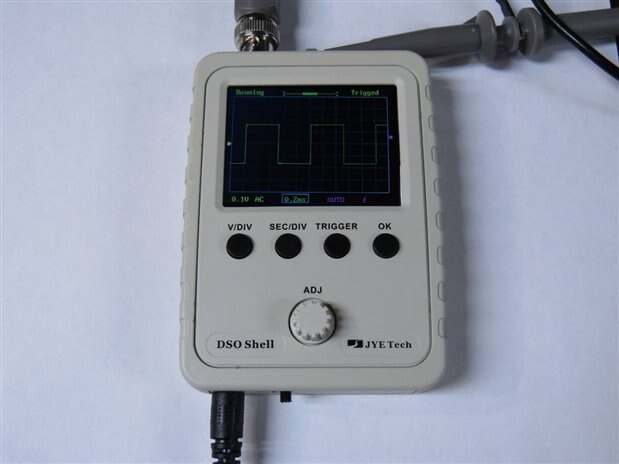
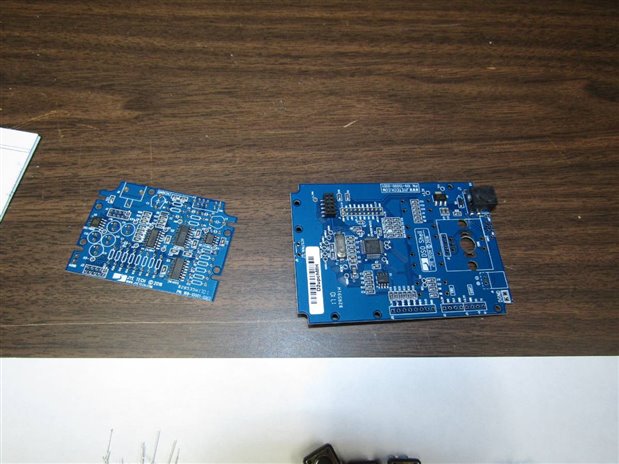
At $22.00 including shipping from China this is a no brainer. With a 200K bandwidth (Perhaps a bit of an exaggeration) it is undersized for many applications but still is a good tool for Audio and lower frequency servicing as well as a good educational tool for the experimenter or enthusiast. This model of the unit comes with all the SMD components installed. The through the hole components, switches and connectors are left for the kit builder. Here is what comes in the package:


image


Note that while you see a probe in some of my pictures this is not included in the kit, nor is the 9 volt power supply. I found that the small wall warts that I use for the Arduinos worked well. I also put a battery pack on the back of one unit so that I have a portable model. The manufacturer cautions that 10 volts is the high limit of the power supply and damage may result if the unit is powered with a higher voltage.


Here are what the circuit boards look like out of the box:


image


The kit comes with 4 pages of assembly instructions, calibration, and operation manual. While it is over all adequate it takes a lot of looking close and a thorough reading to get it right the first time. I have build three so far and I still can't quite get it right. It is not that the correct procedures aren't explained or illustrated somewhere on the pages it is just that it is not a totally smooth sail and I have a tendency to use my intuition too much. Fortunately a couple redos are permitted. The solder points are very small and a little challenging so this may not be a kit for a first time builder. Better to have some soldering experience first though it is doable if someone with experience is supervising a beginner.


image


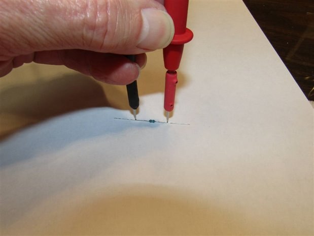
The resistors supplied are very small and 5 banded. My 68 year old eyes had a challenge with them so I just metered them and put them where they belonged. If you happen to have some of my special tungsten carbide meter probe tips you can check 1/8 watt resistors one handed like this:


image


When the main board is fully populated they have you plug it in to check for proper operation. The instructions are a little out of sequence so it is necessary to populate the board and then go back to the first instruction on the list telling you to test it. At this point all one can do it see the screen and toggle the function buttons.


image


I found that the vias did not pull the solder in quite as easily as I would have liked so a good inspection of both sides of the board after soldering allowed me to dress up a couple questionable looking joints. The Analog board is the board where the bulk of the through the hole components must be installed. Over all the instructions were good and the components easy to identify. On the first two units that I built I mounted the adjust control backwards on its board. This does not harm anything but the unit will not work properly. If the instructions are read carefully they have a small box with a red print warning not to do it the way I did. Once this error was corrected both of the first two units worked properly. Here is the small board showing the side not to mount the control on.


image


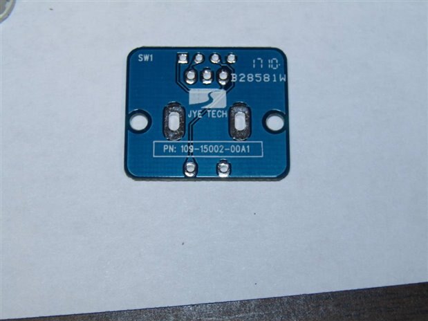
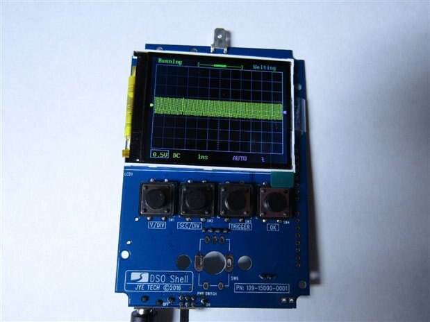
The analog board comes with two sets of header pins so that during calibration the main board can be off set to allow access to the adjustments. While in this position one can check voltages and tune the input to display a clean square wave.


image


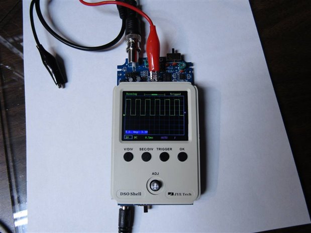
One feature that I was really pleased with is the ability to toggle on and off a list of measurements. Usually on a meter this size and cost one is left to guess what the digital data is. Here is what the unit looks like with the measurements displayed:


image


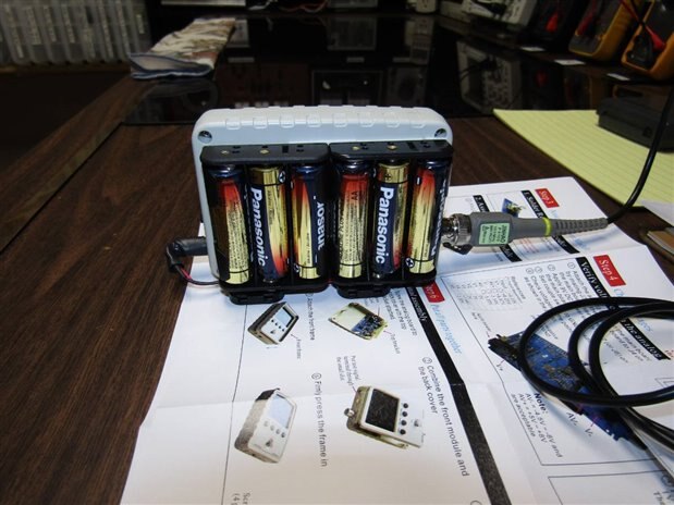
I put a battery pack on the back of one unit to make it more portable and purchased a set of $10.00  Oscilloscope probes for the units. The probes like the oscilloscopes came with free shipping but this time the Chinese had them shipped to me from the Seychelles. The ways of the electronics world are hard to believe. I am enjoying this era of free trade and exchange of products. I wonder how long before the politicians see what is going on and screw everything up. Any how if you like to build things this was a fun little project with very little financial risk involved. Here is a picture of the back of my unit with the battery pack and a picture of a completed unit.


image


image


Have Fun.


John

  • Sign in to reply

Top Comments

  • jw0752
    jw0752 over 8 years ago +7
    Final Chapter: One of the points of having a small Oscilloscope like this one is to make it portable. I went looking for a suitable battery pack for its 8V to 10V power needs. I also wanted the pack to…
  • jw0752
    jw0752 over 8 years ago in reply to mcb1 +5
    Hi Mark, Here is the bandwidth analysis in pictures. The max Horizontal sweep speed of the small scope is 10 uS/Div. so I put both scopes on this setting and stepped the frequency from 10 kHz to 240 kHz…
  • jw0752
    jw0752 over 8 years ago in reply to balearicdynamics +4
    Hi Enrico, Here is a closeup of the processor and what I believe to be the data bus to the processor. Perhaps that will tell you more about how accessible the software is. John
Parents
  • mcb1
    mcb1 over 8 years ago

    Nice find.


    have you tried to see what the bandwidth is ??

    With a 200K bandwidth (Perhaps a bit of an exaggeration)


    • Cancel
    • Vote Up +1 Vote Down
    • Sign in to reply
    • More
    • Cancel
  • jw0752
    jw0752 over 8 years ago in reply to mcb1

    Hi Mark,

    Here is the bandwidth analysis in pictures. The max Horizontal sweep speed of the small scope is 10 uS/Div. so I put both scopes on this setting and stepped the frequency from 10 kHz   to 240 kHz.


    image


    image


    image


    image


    image


    image


    John

    • Cancel
    • Vote Up +5 Vote Down
    • Sign in to reply
    • More
    • Cancel
  • jc2048
    jc2048 over 8 years ago in reply to jw0752

    I'd have thought that the connector you show (J1) was likely to be the LCD panel interface.


    J3 down the other edge is an SWD programming interface [it says so next to it, so even a non-expert like me can tell].

    • Cancel
    • Vote Up +1 Vote Down
    • Sign in to reply
    • More
    • Cancel
  • jc2048
    jc2048 over 8 years ago in reply to jc2048

    If the firmware is available, then it would lend itself nicely to hacking.


    Increase to two or four channels [or be a rebel, ignore convention, and go for 3 or 5 channels].

    XY plotting.
    Curve tracer.
    The all-singing all-dancing deluxe chrome-plated copper-bottomed brass-necked gold-standard super-duper transistor tester [what brought that one to mind?].
    Crude audio spectrum analyser [via FFT].
    Even cruder rf spectrum analyser [perhaps by hacking an old tv tuner as the front end].


    Does anyone have any other ideas?

    • Cancel
    • Vote Up +2 Vote Down
    • Sign in to reply
    • More
    • Cancel
  • michaelkellett
    michaelkellett over 8 years ago in reply to jc2048

    It doesn't look as if the source code is (or is planned to be) fully available - JYE Tech talk about keeping some in libraries and that would include the data acquisition core.


    If you will end up completely re-writing the code (as you would need to for multiple channels) then you might as well go for better hardware.


    Right now you could use an STM32F767VIT6, the chip will cost you about £10 but it will clock at 216MHz, has 512k of RAM and 3 ADCs and 2 DACs - so it could do three channels at 2.4MHz max sampling rate.

    If you wait for the H7 you get twice the RAM and twice the speed.


    MK

    • Cancel
    • Vote Up +3 Vote Down
    • Sign in to reply
    • More
    • Cancel
  • balearicdynamics
    balearicdynamics over 8 years ago in reply to michaelkellett

    Mike, sure hacking too much it is not the worth, but a bit maybe. All depends on what the producer is happy to release for hackers-developers. image


    Enrico

    • Cancel
    • Vote Up 0 Vote Down
    • Sign in to reply
    • More
    • Cancel
  • jw0752
    jw0752 over 8 years ago in reply to jc2048

    Hi Jon,

    If you are a non-expert then I am a noobie. With you in the expert category however I at least get to qualify as a Tech.  I was just thinking if I could get you guys to pool the fees you would normally charge for all this high tech consulting we could buy a real oscilloscope and put this toy on the shelf.

    John

    • Cancel
    • Vote Up +3 Vote Down
    • Sign in to reply
    • More
    • Cancel
Comment
  • jw0752
    jw0752 over 8 years ago in reply to jc2048

    Hi Jon,

    If you are a non-expert then I am a noobie. With you in the expert category however I at least get to qualify as a Tech.  I was just thinking if I could get you guys to pool the fees you would normally charge for all this high tech consulting we could buy a real oscilloscope and put this toy on the shelf.

    John

    • Cancel
    • Vote Up +3 Vote Down
    • Sign in to reply
    • More
    • Cancel
Children
  • balearicdynamics
    balearicdynamics over 8 years ago in reply to jw0752

    Hey John, please exclude me image

    I am happy with a lot of features and very stable and good performances with my Bitscope on the PI, Mac, Windows ... image (<< 100$)


    Enrico

    • Cancel
    • Vote Up 0 Vote Down
    • Sign in to reply
    • More
    • Cancel
  • jc2048
    jc2048 over 8 years ago in reply to jw0752

    I've never, ever used an ST ARM part, so I'm genuinely a non-expert in them. I have come across 'SWD' elsewhere (I think it's probably Single-Wire Debugging, or something like that - presumably it's an ARM standard rather than something specific to ST) which is how I recognised it.


    I like the aliasing with the 238kHz input (it's kind of beautiful and awful at the same time) but why is the beat frequency 10kHz, or so? That would put the sampling at 250k, rather than the max 1Msps they give, wouldn't it?

    • Cancel
    • Vote Up +1 Vote Down
    • Sign in to reply
    • More
    • Cancel
element14 Community

element14 is the first online community specifically for engineers. Connect with your peers and get expert answers to your questions.

  • Members
  • Learn
  • Technologies
  • Challenges & Projects
  • Products
  • Store
  • About Us
  • Feedback & Support
  • FAQs
  • Terms of Use
  • Privacy Policy
  • Legal and Copyright Notices
  • Sitemap
  • Cookies

An Avnet Company © 2025 Premier Farnell Limited. All Rights Reserved.

Premier Farnell Ltd, registered in England and Wales (no 00876412), registered office: Farnell House, Forge Lane, Leeds LS12 2NE.

ICP 备案号 10220084.

Follow element14

  • X
  • Facebook
  • linkedin
  • YouTube