element14 Community
element14 Community
    Register Log In
  • Site
  • Search
  • Log In Register
  • About Us
  • Community Hub
    Community Hub
    • What's New on element14
    • Feedback and Support
    • Benefits of Membership
    • Personal Blogs
    • Members Area
    • Achievement Levels
  • Learn
    Learn
    • Ask an Expert
    • eBooks
    • element14 presents
    • Learning Center
    • Tech Spotlight
    • STEM Academy
    • Webinars, Training and Events
    • Learning Groups
  • Technologies
    Technologies
    • 3D Printing
    • FPGA
    • Industrial Automation
    • Internet of Things
    • Power & Energy
    • Sensors
    • Technology Groups
  • Challenges & Projects
    Challenges & Projects
    • Design Challenges
    • element14 presents Projects
    • Project14
    • Arduino Projects
    • Raspberry Pi Projects
    • Project Groups
  • Products
    Products
    • Arduino
    • Avnet Boards Community
    • Dev Tools
    • Manufacturers
    • Multicomp Pro
    • Product Groups
    • Raspberry Pi
    • RoadTests & Reviews
  • Store
    Store
    • Visit Your Store
    • Choose another store...
      • Europe
      •  Austria (German)
      •  Belgium (Dutch, French)
      •  Bulgaria (Bulgarian)
      •  Czech Republic (Czech)
      •  Denmark (Danish)
      •  Estonia (Estonian)
      •  Finland (Finnish)
      •  France (French)
      •  Germany (German)
      •  Hungary (Hungarian)
      •  Ireland
      •  Israel
      •  Italy (Italian)
      •  Latvia (Latvian)
      •  
      •  Lithuania (Lithuanian)
      •  Netherlands (Dutch)
      •  Norway (Norwegian)
      •  Poland (Polish)
      •  Portugal (Portuguese)
      •  Romania (Romanian)
      •  Russia (Russian)
      •  Slovakia (Slovak)
      •  Slovenia (Slovenian)
      •  Spain (Spanish)
      •  Sweden (Swedish)
      •  Switzerland(German, French)
      •  Turkey (Turkish)
      •  United Kingdom
      • Asia Pacific
      •  Australia
      •  China
      •  Hong Kong
      •  India
      •  Korea (Korean)
      •  Malaysia
      •  New Zealand
      •  Philippines
      •  Singapore
      •  Taiwan
      •  Thailand (Thai)
      • Americas
      •  Brazil (Portuguese)
      •  Canada
      •  Mexico (Spanish)
      •  United States
      Can't find the country/region you're looking for? Visit our export site or find a local distributor.
  • Translate
  • Profile
  • Settings
Personal Blogs
  • Community Hub
  • More
Personal Blogs
John Wiltrout's Blog Christmas Vacation Project - Building a Clap Switch Light
  • Blog
  • Documents
  • Mentions
  • Sub-Groups
  • Tags
  • More
  • Cancel
  • New
  • Share
  • More
  • Cancel
Group Actions
  • Group RSS
  • More
  • Cancel
Engagement
  • Author Author: jw0752
  • Date Created: 27 Dec 2017 5:36 AM Date Created
  • Views 3851 views
  • Likes 14 likes
  • Comments 24 comments
  • clap_switch
  • holidayspecialch
Related
Recommended

Christmas Vacation Project - Building a Clap Switch Light

jw0752
jw0752
27 Dec 2017

Thanks to Christmas Vacation I had the opportunity to spend the day doing electronics with my 11 year old Grandson Ivan. We began with a small Chinese noise actuated clap switch.


https://www.ebay.com/itm/VOS-Voice-Operated-Switch-DIY-Kit-Voice-Switch-Electronic-Production-Suite/222649153280?hash=item33d6ec7700:g:1cAAAOSwnDZT5G~0


image


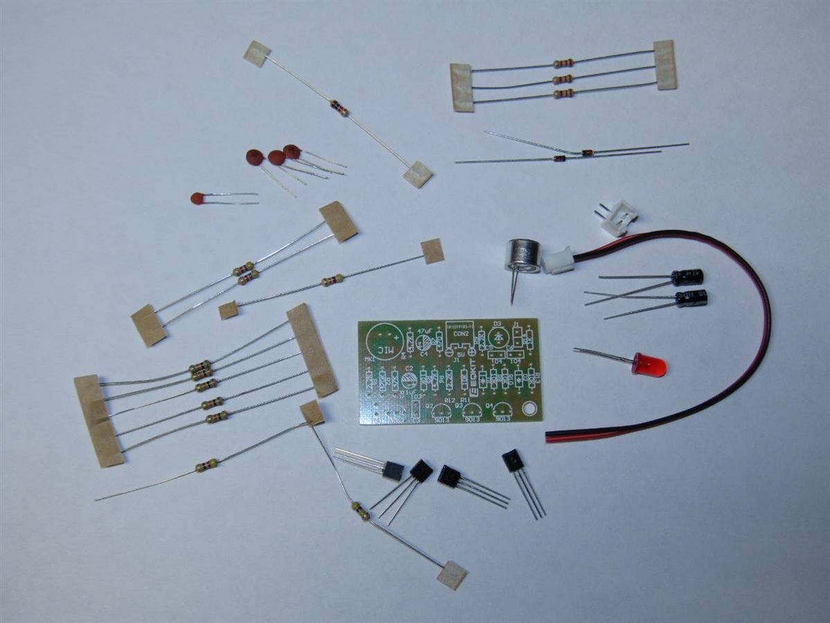
As you can see the kit comes with no directions other than the silk screening on the board. I had explored this kit a while back and reverse engineered a schematic so Ivan had that as a guide as well.


image


It is a simple 2 stage audio amplifier that triggers a transistor flip flop which in turn lights a small LED. It is designed to operate at 5 volts. Ivan has become very adept at building these Chinese kits and he is also knowledgeable about my shop. With few exceptions I just turn him loose and let him work. Today at one point he got too much solder on the board so that two pads were bridged. I did not realize this until I saw that he had retrieved the solder wick from the drawer and was making the proper remedy to the problem. As he worked we discussed how we could take this simple, not so practical, circuit and make something useful out of it. The idea came up that he would like a light by his bed so that when he got up at night he could just clap and have light.  I began to check for resources in the shop and found a small 2 watt 12 volt LED panel, a 12 volt linear wall wart, a project box of the right size, a nice prototyping board, and a power switch. Since we would be building the kit to integrate with the rest of the components I told Ivan to leave the microphone and power jack off the board. We would mount them to the project box when we assembled the whole unit.


I made a simple drawing of the support circuitry we would need to run the 12 volt LED panel and the 5 volt kit. Due to the design of the kit it would also be necessary to invert the output of the kit so that we would sync the LED panel with the small red LED on the kit board that was being driven directly from the flip flop. Since my hand drawing doesn't scan very well I have made a quick schematic.


image


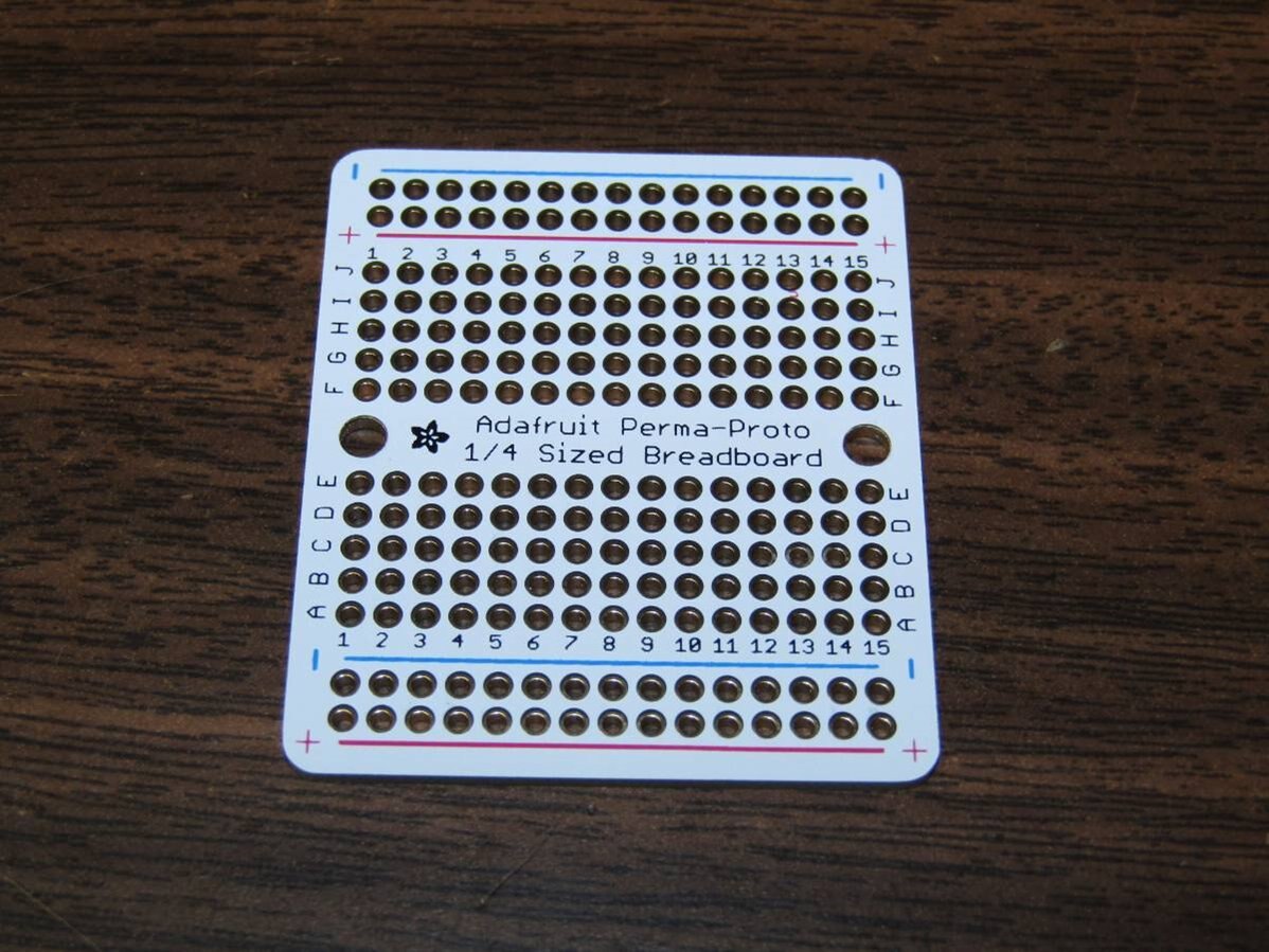
As Ivan continued to work on the kit, he was decoding the color codes of the resistor at this point, I started to bread board the support circuit just to make sure it would work and also to give Ivan the layout so he could directly transfer it onto the prototype board. I love the Adafruit prototyping boards that have the same layout as a bread board and this makes simple work of transferring a layout.


image


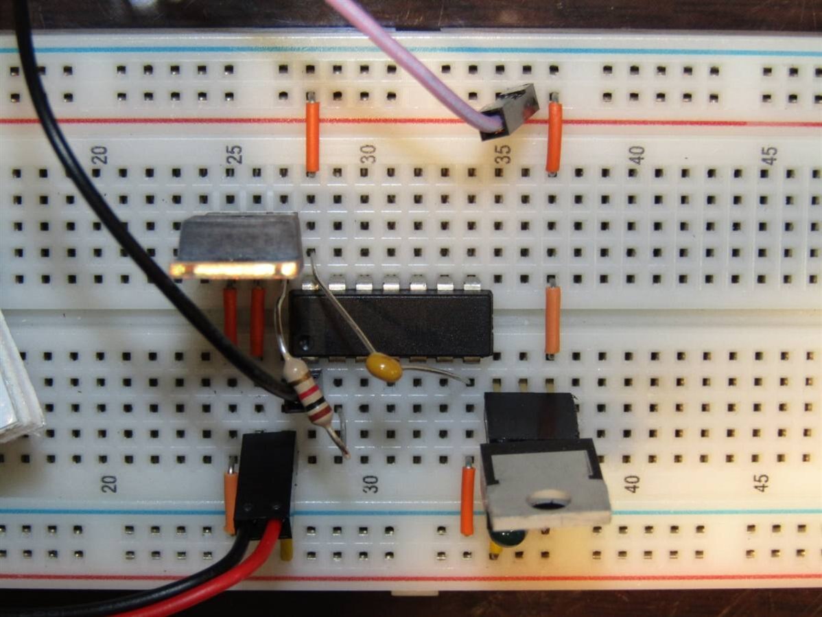
Here was the bread board layout which seemed to work using the sample Clap Switch circuit I had built a couple weeks earlier.


image


After Ivan finished with the kit board he began to work on the support board. I helped by placing components and he soldered them in place. Since we were approaching 4 hours interrupted only by lunch I asked him if he was getting tired of electronics and he said no. I want this to be fun for him and not a job so I try to be conscious of his interest level. He stays so focused and interested I frankly forget that he is only eleven. I apologize that I did not get better pictures of the final assembly. Due to the difficulty of holding wires in place I would be the one to hold them and he continued to solder them. Here is a picture of the boards in the completed project box as well as a picture of the unit finished.


image


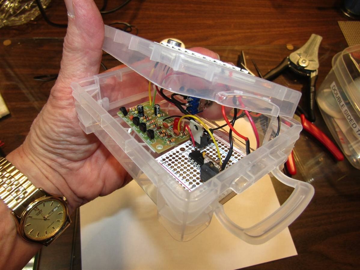
We had mounted the LED array and the Microphone on top of the box and the main switch was on the back where the wire from the 12 volt wall wart entered.


image


Here is a short video of Ivan demonstrating the Clap Switch Light for you.


You don't have permission to edit metadata of this video.
Edit media
x
image
Upload Preview
image


The actual bench time for building this small project today was over 5 hours. Ivan's focus and enthusiasm made every minute a joy.


Happy Grandpa

John


  • Sign in to reply

Top Comments

  • genebren
    genebren over 7 years ago in reply to genebren +5
    Still, not quite at the stage were she is interested in electronics, but here is my granddaughter holding a Pez dispenser (Snoppy) and a pair of philips screwdrivers. She kept looking for screws to turn…
  • jw0752
    jw0752 over 7 years ago in reply to jc2048 +4
    Hi Jon, The reason we didn't implement this excellent idea is that Old Grandpa thinks too linearly. This is exactly what I love about this forum and sharing with you guys. I will go back to the circuit…
  • ntewinkel
    ntewinkel over 7 years ago +4
    What a great project! And the customization makes it that much better with an even greater sense of accomplishment at the end. You can tell Ivan is really proud of the result! -Nico
Parents
  • jc2048
    jc2048 over 7 years ago

    Cool! Sound, light, and transistors - almost the perfect project.


    Why the inverter? Why not drive the MOSFET with the other side of the bistable, or doesn't that work for some reason?

    • Cancel
    • Vote Up +2 Vote Down
    • Sign in to reply
    • More
    • Cancel
  • jw0752
    jw0752 over 7 years ago in reply to jc2048

    Hi Jon,


    The reason we didn't implement this excellent idea is that Old Grandpa thinks too linearly. This is exactly what I love about this forum and sharing with you guys. I will go back to the circuit in the next couple days and try to take the drive for the MOSFET from the other side of the FLIP FLOP. This also gives me the opportunity to show Ivan that there are always several ways to accomplish a goal and that the first that comes to mind isn't always the best.


    John

    • Cancel
    • Vote Up +4 Vote Down
    • Sign in to reply
    • More
    • Cancel
  • mcb1
    mcb1 over 7 years ago in reply to jw0752

    My first thought was to use an Optocoupler, but you'd still need the MosFET to drive the LED's....

    You can drive it either in parallel or series with the on-board LED.


    jw0752

    The reason we didn't implement this excellent idea is that Old Grandpa thinks too linearly

    I don't think it has anything to do with 'Old'.

    It's a matter of exploring all available options before deciding on the best/easist one to use.

    Sometimes we forget to look at the options and focus on the first solution that comes to us.


    Mark

    • Cancel
    • Vote Up +1 Vote Down
    • Sign in to reply
    • More
    • Cancel
  • Jan Cumps
    Jan Cumps over 7 years ago in reply to jw0752

    I have that too, John. Once my brain tunnels in a particular direction.

    Nothing can replace a multitude of thinkers - some additional eyes to look at the problem ....

    • Cancel
    • Vote Up +2 Vote Down
    • Sign in to reply
    • More
    • Cancel
  • jw0752
    jw0752 over 7 years ago in reply to mcb1

    I briefly looked at putting it in place of the on board but its need for 12 volts and 200 mA definitely puts it on a separate circuit with a MOSFET driver. I on board LED is part of the bistable and so I didn't mess with it.


    In hind sight I like to believe that I would have thought of it if I had taken the time to think but then again I have continued to do the same dumb things for decades sometimes before it suddenly dawns on me to do them differently.


    John

    • Cancel
    • Vote Up +1 Vote Down
    • Sign in to reply
    • More
    • Cancel
  • jw0752
    jw0752 over 7 years ago in reply to Jan Cumps

    The power of collaboration is very powerful and a lot of fun. When I was a kid I had a friend who would come to visit his grandmother in the summer. We were great collaborators and spent all of our time building go-carts out of wood and do nothing machines out of old electronics and a lot of things I dare not mention. After we grew up we lived in different cities and I haven't had that feeling of collaboration again until I started hanging out with you guys.


    Thanks

    John

    • Cancel
    • Vote Up +2 Vote Down
    • Sign in to reply
    • More
    • Cancel
  • jc2048
    jc2048 over 7 years ago in reply to jw0752

    It's much more obvious that you have the choice of two complementary outputs if the bistable is drawn in the traditional way like this


    image


    Are you sure your schematic is correct with R13 going to the rail like that? The flip-flop would be stuck in just one of the states and not get to the other.

    • Cancel
    • Vote Up +2 Vote Down
    • Sign in to reply
    • More
    • Cancel
Comment
  • jc2048
    jc2048 over 7 years ago in reply to jw0752

    It's much more obvious that you have the choice of two complementary outputs if the bistable is drawn in the traditional way like this


    image


    Are you sure your schematic is correct with R13 going to the rail like that? The flip-flop would be stuck in just one of the states and not get to the other.

    • Cancel
    • Vote Up +2 Vote Down
    • Sign in to reply
    • More
    • Cancel
Children
  • jw0752
    jw0752 over 7 years ago in reply to jc2048

    Hi Jon,


    I decided it would be a good exercise for me to redo the schematic and put the bistable into a proper configuration. I also hooked up the circuit again and took readings of the base of Q1 and the collector of Q2 with the oscilloscope to illustrate what you were describing in your post.


    image


    image


    The Channel 2 is the base of Q1 and Channel 1 is the collector of Q2. Trigger is on the falling edge of Ch 1.


    John

    • Cancel
    • Vote Up +2 Vote Down
    • Sign in to reply
    • More
    • Cancel
element14 Community

element14 is the first online community specifically for engineers. Connect with your peers and get expert answers to your questions.

  • Members
  • Learn
  • Technologies
  • Challenges & Projects
  • Products
  • Store
  • About Us
  • Feedback & Support
  • FAQs
  • Terms of Use
  • Privacy Policy
  • Legal and Copyright Notices
  • Sitemap
  • Cookies

An Avnet Company © 2025 Premier Farnell Limited. All Rights Reserved.

Premier Farnell Ltd, registered in England and Wales (no 00876412), registered office: Farnell House, Forge Lane, Leeds LS12 2NE.

ICP 备案号 10220084.

Follow element14

  • X
  • Facebook
  • linkedin
  • YouTube